
Compressors and Air Conditioners

A technology of compressors and pressure plates, which is applied in the direction of machines/engines, mechanical equipment, liquid fuel engines, etc., can solve problems affecting compressor performance, cooling capacity, and reliability, and achieve simple structure, eliminate periodic noise and vibration, and ensure The effect of concentricity

Active Publication Date: 2018-10-02
GREE ELECTRIC APPLIANCES INC
View PDF5 Cites 0 Cited by
  • Summary
  • Abstract
  • Description
  • Claims
  • Application Information

AI Technical Summary

Problems solved by technology

Therefore, the axial movement of the crankshaft of the compressor will cause adverse factors such as noise and vibration to a large extent, and at the same time seriously affect the performance, cooling capacity and reliability of the compressor.

Method used


Image

  • Compressors and Air Conditioners
  • Compressors and Air Conditioners
  • Compressors and Air Conditioners

Examples


Embodiment Construction

[0022] In order to make the objectives, technical solutions and advantages of the present invention clearer, the compressor and the air conditioner of the present invention will be described in further detail below with reference to the accompanying drawings and embodiments. It should be understood that the specific embodiments described here are only used to explain the present invention, but not used to limit the present invention.

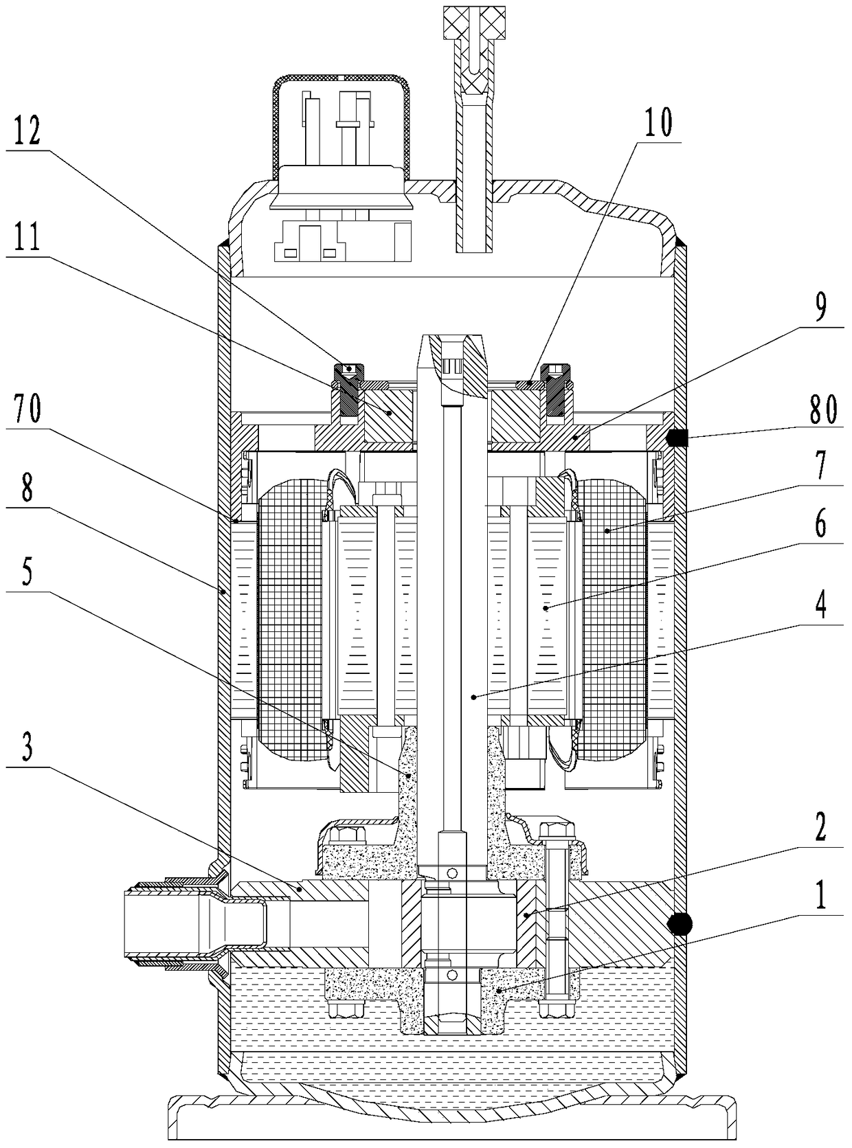
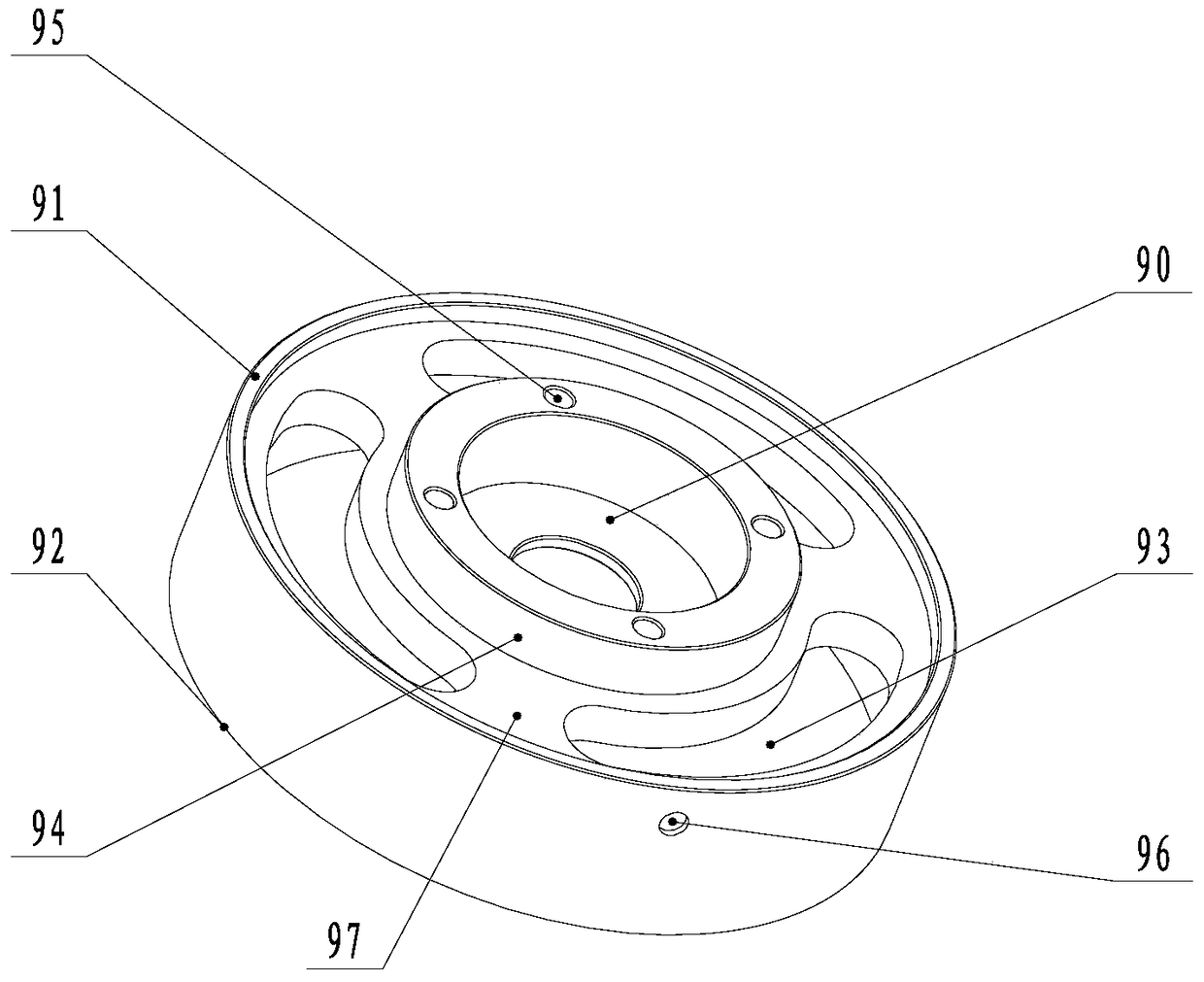
[0023] Reference Figure 2 to Figure 4 , The compressor of an embodiment of the present invention includes a casing 8, and a motor, a lower flange 1, a roller 2, a cylinder 3, a sliding vane (not shown in the figure), a crankshaft 4, an upper Flange 5 and axial movement limiting device. The axial movement limiting device is arranged at the tail end of the crankshaft 4, and the axial movement limiting device includes a supporting seat 9, a bearing 11 and a pressure plate 10. The support base 9 is embedded in the housing 8, and the bearing 11 is ar...


PUM


Abstract

The invention provides a compressor which comprises a motor and a crankshaft. The motor and the crankshaft are arranged in the shell. An axial moving limiting device is arranged at the tail end of the crankshaft and comprises a supporting seat, a bearing and a pressing plate. The supporting seat is inlaid in the shell. The bearing is arranged on the supporting seat. The supporting seat is arranged on the crankshaft in a sleeving manner through the bearing. The pressing plate is fixedly arranged on the supporting seat. The pressing plate is used for limiting the axial movement of the bearing. The invention further relates to an air conditioner. According to the compressor and the air conditioner, the axial moving limiting device is arranged at the tail end of the crankshaft of the compressor, the problem of axial moving of the crankshaft is effectively solved through the bearing and the pressing plate of the axial moving limiting device, the problem of periodical noise vibration of the compressor under some conditions is solved, the axial moving limiting device is simple in structure, convenient to install and high in universality, the problems of radial deflection and eccentricity of the crankshaft are effectively solved, and the coaxility of the whole compressor is ensured.

Description

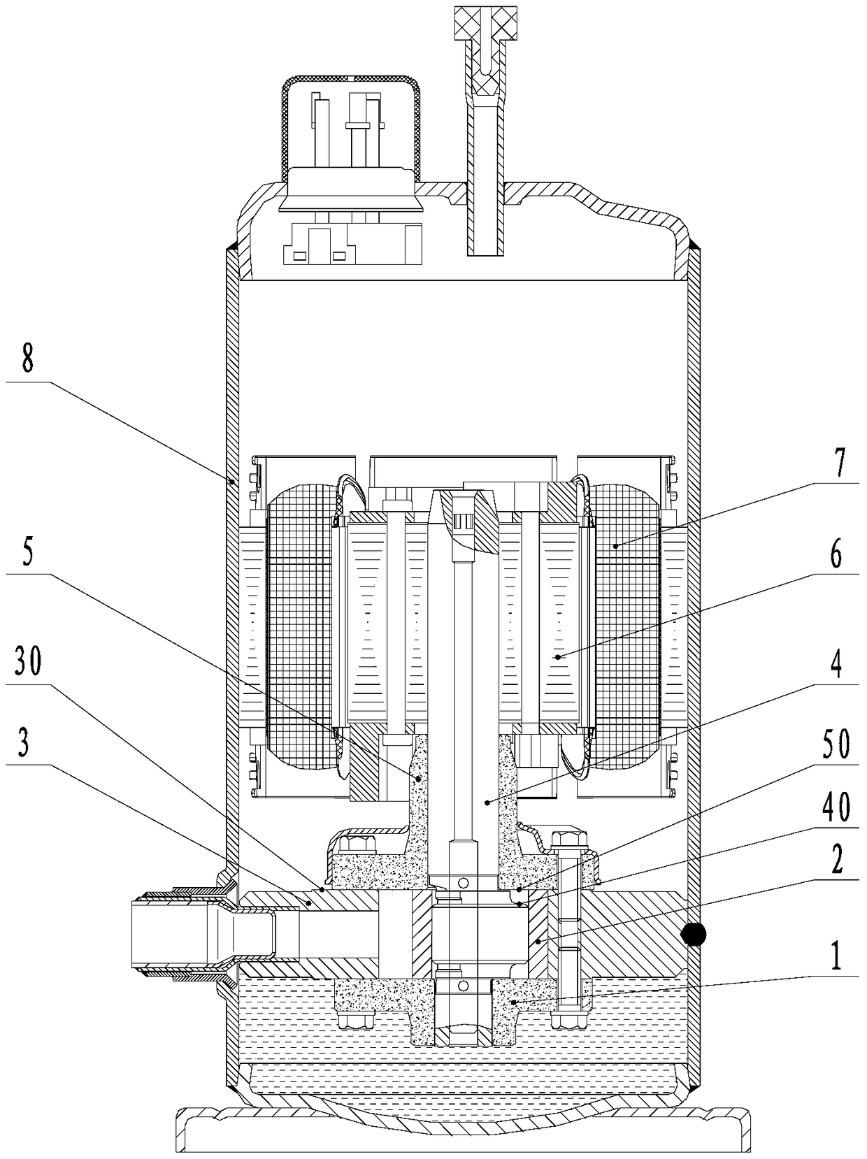
Technical field [0001] The invention relates to the field of refrigeration, in particular to a compressor and an air conditioner. Background technique [0002] Such as figure 1 As shown, the existing rotor compressor includes a lower flange 1, a roller 2, a cylinder 3, a sliding vane (not shown), a crankshaft 4, an upper flange 5, a rotor 6, a stator 7 and a housing 8. And other major components. When the rotor compressor is in operation, the rotor 6 of the motor drives the crankshaft 4 to rotate, which in turn drives the roller 2 to perform periodic rotation in the cylinder 3. The roller 2, the cylinder 3 and the sliding vane form a crescent-shaped suction cavity and an exhaust cavity. With the periodic rotation of the roller 2, the volume of the suction and exhaust cavity changes continuously, and finally completes the suction-compression-exhaust work cycle . [0003] Generally, in the design of a rotary compressor, there is a certain height difference between the upper end su...

Claims


Application Information

Patent Timeline
Patent Type & Authority Patents(China)
IPC IPC(8): F04C29/00
Inventor 殷伟豪黄伟才
Owner GREE ELECTRIC APPLIANCES INC
Learn More