Shaft support structure and compressor

A technology of supporting structure and rotating shaft, which is applied in the field of compression, can solve problems such as crankshaft jamming, and achieve the effect of improving crankshaft jamming

Active Publication Date: 2019-01-22
ZHUHAI LANDA COMPRESSOR +1
View PDF5 Cites 0 Cited by
  • Summary
  • Abstract
  • Description
  • Claims
  • Application Information

AI Technical Summary

Problems solved by technology

[0004] The purpose of the present invention is to provide a rotating shaft support structure and a compressor to solve the problem that the crankshaft is stuck due to the inaccurate installation position of the bracket in the compressor in the prior art

Method used


Image

  • Shaft support structure and compressor
  • Shaft support structure and compressor
  • Shaft support structure and compressor

Examples


no. 1 example

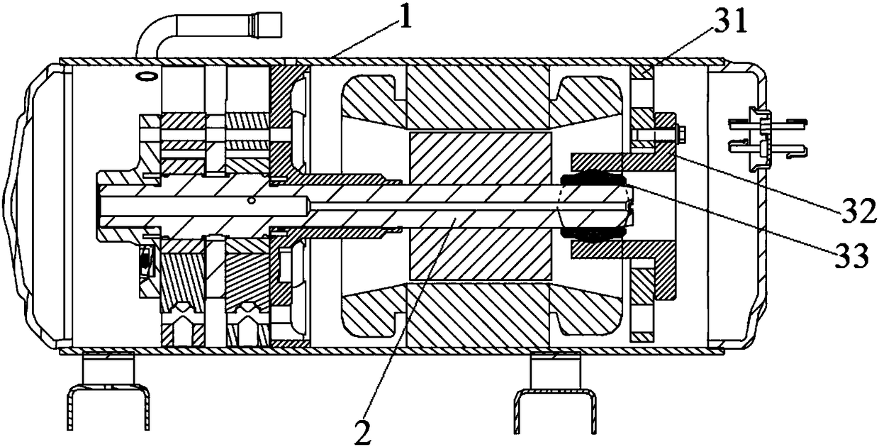
[0044] The following will be based on image 3 and Figure 4 The specific structure of the rotating shaft support structure of the first embodiment of the present invention will be described in detail.

[0045] Such as image 3 As shown, in the first embodiment, the rotating shaft support structure 3 includes a bracket 31 and a position compensation structure. The bracket 31 is fixedly arranged relative to the housing 1 . The rotating shaft 2 is rotatably supported on the bracket 31 . The rotating shaft supporting structure 3 also includes a bearing 32 . The bearing 32 is disposed on the bracket 31 . The bearing 32 is used to support the rotating shaft 2 . The position compensation structure is disposed between the bearing 32 and the rotating shaft 2 .

[0046] Preferably, as image 3 and Figure 4 As shown, the rotating shaft support structure 3 further includes a compensation sleeve 33 arranged between the bearing 32 and the rotating shaft 2 . The compensation slee...

no. 2 example

[0059] Such as Figure 5 As shown, in the second embodiment, the rotating shaft support structure 3 includes a bracket 31 and a position compensation structure. The bracket 31 is fixedly arranged relative to the housing 1 . The rotating shaft 2 is rotatably supported on the bracket 31 . The rotating shaft supporting structure 3 also includes a bearing 32 . The bearing 32 is disposed on the bracket 31 . The position compensation structure is arranged between the bracket 31 and the bearing 32 .

[0060] The bearing 32 includes a support portion for supporting the rotating shaft 2 and a flange connected to the support portion. The position compensation structure can be arranged between the bracket and the supporting part, or between the bracket 31 and the flange.

[0061] In this embodiment, the position compensation structure is arranged between the bracket 31 and the flange. Such as Figure 6 , Figure 7 and Figure 8 As shown, the first mating surface is provided on t...


PUM


Abstract

The invention discloses a rotating shaft supporting structure and a compressor. The rotating shaft supporting structure comprises a support and a position compensation structure; the support is fixedly arranged relative to a shell; a rotating shaft is supported on the support in a rotating mode; and the position compensation structure comprises a first matching surface arranged on the support and a second matching surface arranged on the rotating shaft, the rotating shaft is supported on the support through matching between the first matching surface and the second matching surface, one of the first matching surface and the second matching surface is a first rotation surface with the center protruding out towards the other matching surface, the generatrix of the first rotation surface is a smooth curve, and a rotation axis is arranged along an axis of the rotating shaft. According to the rotating shaft supporting structure, when the installation position of the support is inaccurate, the rotating shaft can be still supported on the support without being jammed by adjusting the abutting position of the first matching surface and the second matching surface.

Description

technical field [0001] The invention relates to the technical field of compression, in particular to a rotating shaft support structure and a compressor. Background technique [0002] Such as figure 1 As shown, the horizontal compressor in the prior art includes a casing 1', a crankshaft 2', a bracket 3' and a bearing 4'. The outer side of the bracket 3' is welded on the housing 1' and the bracket 3' supports the crankshaft 2' through the bearing 4'. [0003] Among them, the coaxiality between the inner hole of the bearing 4' and the crankshaft 2' is very important. For example, if figure 2 As shown, when there is a problem with the verticality between the axis of the bracket 3' and the crankshaft 2', that is to say, when the installation position of the bracket 3' is inaccurate, the inner hole of the bearing 4' and the crankshaft 2' cannot be coaxial, The bearing 4' will block the crankshaft 2' and affect the rotation of the crankshaft 2'. Contents of the invention ...

Claims


Application Information

Patent Timeline
Patent Type & Authority Patents(China)
IPC IPC(8): F16C35/10F16C23/04F04C29/00
CPCF04C29/00F16C23/043F16C35/10F16C2360/42
Inventor 谢利昌刘达炜吕浩福范少稳
Owner ZHUHAI LANDA COMPRESSOR
Why Eureka
Try Eureka