Autonomous cleaning equipment

A technology of cleaning equipment and free ends, applied in cleaning equipment, cleaning machinery, carpet cleaning, etc., can solve the problems of increased load, stuck cleaning robot, and reduced service life of the driving wheel power mechanism, etc., to achieve quick installation, low failure rate, Prevents the effect of excessive range of motion

Pending Publication Date: 2021-03-19
SHENZHEN SILVER STAR INTELLIGENT TECH CO LTD
View PDF12 Cites 0 Cited by
  • Summary
  • Abstract
  • Description
  • Claims
  • Application Information

AI Technical Summary

Problems solved by technology

[0003] The installation method of the sensing component adopts a fixed connection, and the fixed connection type is fixed by a threaded connection, and the fixed connection protective cover is threadedly connected with the housing, and the sensing component is protected by the protective cover, which protrudes from the top wall of the housing. When the fixedly connected protective cover enters a low position such as a sofa, the bottom of a bed, etc., the cleaning robot may be stuck in the low position, which causes the cleaning robot to continue to run on the original running path in this position, not only unable to continue cleaning work , will increase the load on the power mechanism of the walking wheel of the cleaning robot and reduce the service life of the power mechanism of the walking wheel

Method used


Image

  • Autonomous cleaning equipment
  • Autonomous cleaning equipment
  • Autonomous cleaning equipment

Examples


Embodiment

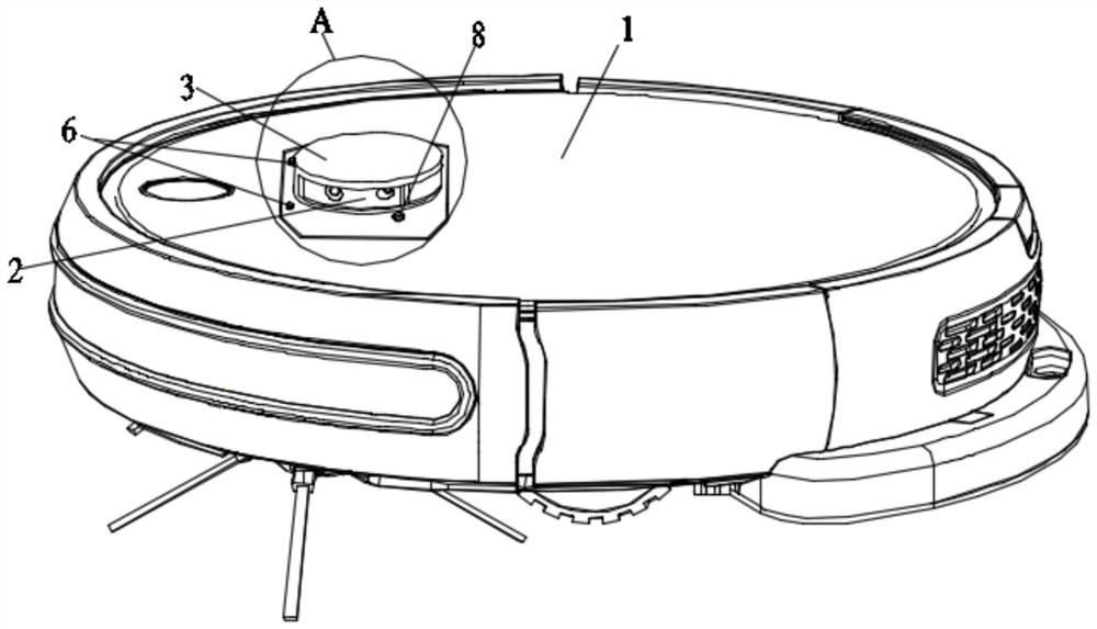
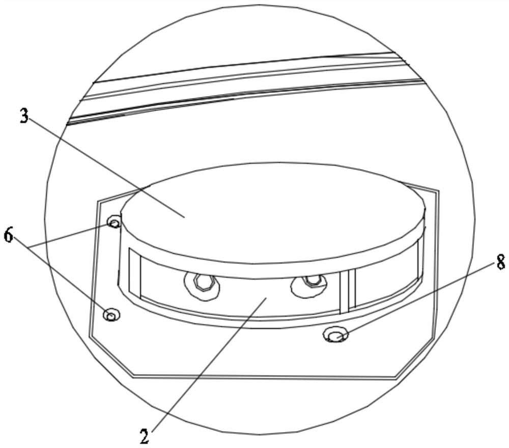
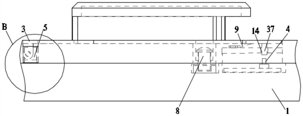
[0053] Such as Figure 1 to 3 Distance figure 1 It is a structural diagram of the autonomous cleaning device of the present invention, figure 2 Yes figure 1 Local enlargement diagram of the in the region A, image 3 A schematic diagram of the connection between the cover and the switch.

[0054] Self-cleaning equipment of the present invention, including:

[0055] Housing 1, the housing 1 can include a housing and a lower casing, which can be used to mount the preceding collision assembly, walking assembly, cleaning assembly, control unit, and water tank assembly.

[0056] Perception assembly 2, the housing 1 is provided with a perceptual assembly 2 that is electrically connected to the control unit, and the perceptual assembly 2 protrudes from the housing 1 to perceive environmental information around the autonomous cleaning equipment; The perceptual assembly 2 can be a sensor such as a laser radar, a TOF sensor, a structural light, an ultrasonic sensor, which may be a single ...


PUM


Abstract

The invention relates to the field of cleaning equipment, in particular to self-cleaning equipment. A positioning piece is arranged, the positioning piece is detachably and fixedly connected with a shell, the positioning piece is also hinged with a cover body, so that the positioning piece with the cover body is connected to the shell in a positioning manner, the cover body can rotate relative tothe shell, the shell is provided with a positioning part, and the positioning piece is matched with the positioning part. Specifically, the free end of the cover body is located on the side close to the moving direction of the self-cleaning equipment, a switch electrically connected with the control part is arranged on a moving path located at the free end of the cover body, a sensing assembly ofthe self-cleaning equipment is located in the cover body, the cover body plays a role in protection, and when the self-cleaning equipment enters a low position such as a sofa, the cover body rotates downwards due to stress; the free end can trigger the switch, the switch sends out a conduction signal after being triggered, the control part can receive the conduction signal to control the self-cleaning equipment to act, and the problem that the self-cleaning equipment is continuously stuck at a low position is greatly solved.

Description

Technical field [0001] The present invention relates to the field of cleaning equipment, and more particularly to an autonomous cleaning device. Background technique [0002] A commonly cleaning robot's perceptual component is a single or plurality of combined perceptual elements, and the perceptual assembly can protrude from the top wall of the housing of the robot to perceive environmental information around the cleaning robot. [0003] The mounting method of the perception component is fixed by a fixed connection, and the fixed connection is fixed by a threaded connection, and the sensing component is protected by setting a fixed connection protective cover, and the protective cover is protected, protecting the top wall of the housing, When the fixed-connected protective cover is in low position such as the sofa, the bottom of the bed, it may cause the cleaning robot to kill at the low position, which causes the cleaning robot to operate in the position of the original operati...

Claims


Application Information

Patent Timeline
Patent Type & Authority Applications(China)
IPC IPC(8): A47L11/24A47L11/40
CPCA47L11/24A47L11/40A47L11/4008A47L11/4011
Inventor 郑连荣
Owner SHENZHEN SILVER STAR INTELLIGENT TECH CO LTD
Why Eureka
Try Eureka