Door assembly for substrate processing chamber

a technology for processing chambers and substrates, applied in the field of door assemblies, can solve the problems of reducing overall processing efficiency, etch byproduct accumulation on the walls of the processing chambers, and affecting the processing quality, so as to prevent or tighten the seal, the effect of inhibiting or preventing the formation of stringers

Active Publication Date: 2015-06-30
STMICROELECTRONICS SRL
View PDF5 Cites 0 Cited by
  • Summary
  • Abstract
  • Description
  • Claims
  • Application Information

AI Technical Summary

Benefits of technology

[0009]In some embodiments, a processing apparatus includes a door assembly with an entrance adapted to promote sticking of processing byproducts. The entrance includes one or more patterns of features that cooperate to enhance sticking of built-up solid material to ensure that the built-up material remains attached to the entrance. In certain embodiments, a pattern of features is positioned along a tunnel of the entrance. The pattern of features extends across the top of the tunnel or any other portion of the tunnel in which material may be accumulated in the features. The features, in some embodiments, inhibit the formation of stringers or other obstructions that often form in traditional door tunnels. Substrates moved through the tunnel pass below built-up material securely adhered to the features.
[0011]A front portion of the grid door tunnel has a wide surface for mating with the door instead of a traditional raised edge. The enlarged door physically contacts the wide surface to form a tighter seal than conventional seals. The seal between the enlarged door and the wide surface is easily maintained with little to no adjustment to the door. This further inhibits or prevents the formation of stringers.

Problems solved by technology

Wafer etching processes performed within conventional processing chambers often result in the accumulation of etch byproducts on walls of the processing chambers, as well as on other exposed components.
Accumulated byproducts can impair processing quality and can reduce overall processing efficiency, thereby leading to reduced throughput.
These deposits tend to peel and form flakes.
Additional polymer byproduct may be deposited on the flakes and cause additional peeling that ultimately results in large hanging formations commonly referred to as “stringers.” Stringers may obstruct door tunnels and may scratch the top surfaces of wafers.
These types of scratches may result in a significant yield loss, for example, about a 5% yield loss per each scratched wafer. FIG. 1 shows a stringer 50 hanging downwardly into a door tunnel 54.
It may be difficult to load and unload the chamber without damaging wafers, especially if more than one stringer forms along the tunnel 54.
Fabrication processes, such as metal etching, tend to produce significant amounts of byproducts that lead to the formation of stringers.
These etching processes often result in etch byproducts that produce relatively large stringers within about a few hundred RF hours.
If the leak is detected, it may be difficult to reposition the door to eliminate the leak.
Unfortunately, it is difficult to open and close door assemblies repeatedly with the required high level of accuracy.
Dry cleaning operations are often unsuitable for removing large buildups, such as stringers in the door tunnels.
Wet cleaning operations result in significant down-time and, thus, reduce processing throughput.

Method used


Image

  • Door assembly for substrate processing chamber
  • Door assembly for substrate processing chamber
  • Door assembly for substrate processing chamber

Examples


Embodiment Construction

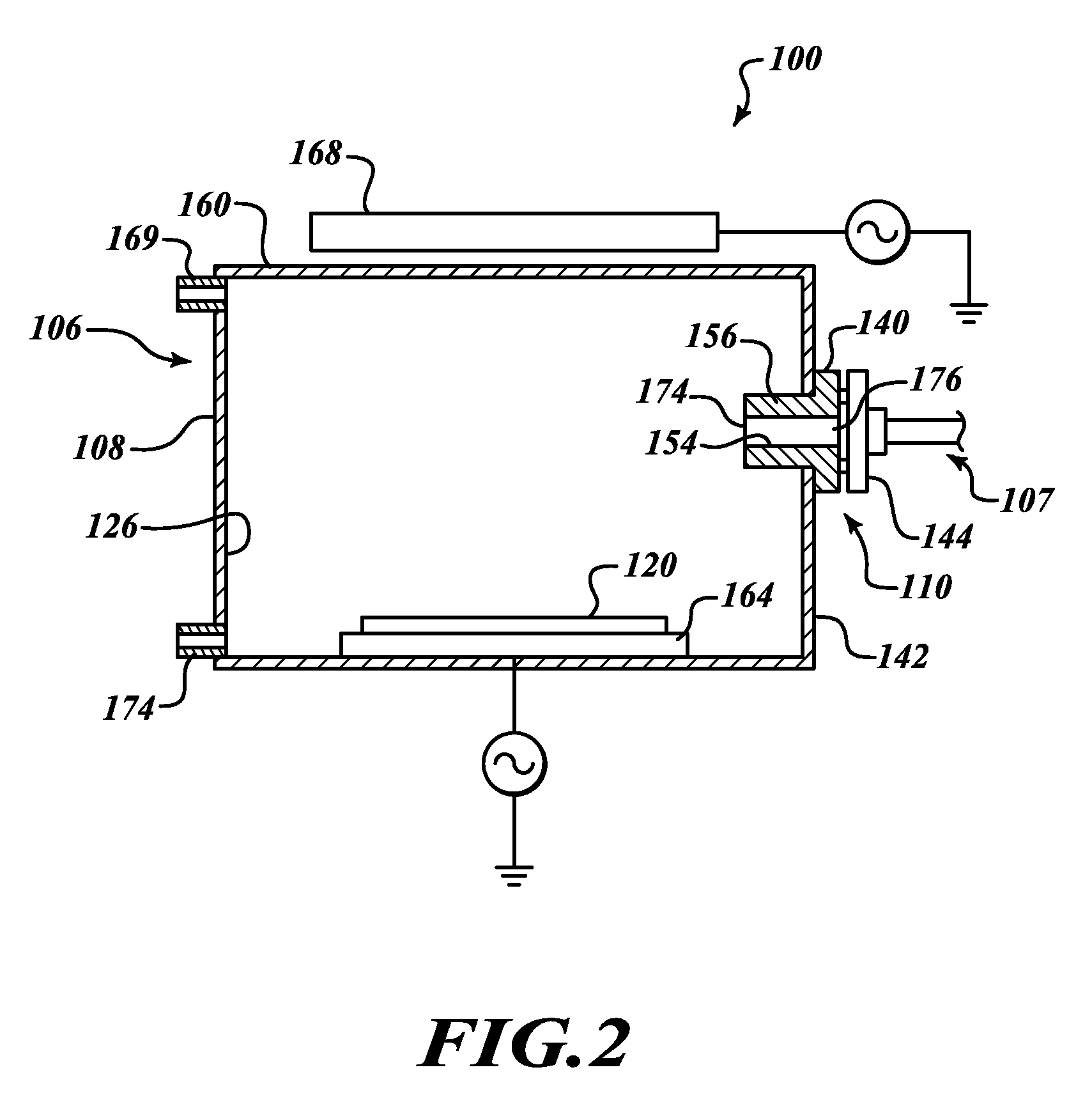
[0027]FIG. 2 shows a substrate processing apparatus 100 including a processing chamber 106 and a door handler 107. The processing chamber 106 includes an enclosure 108 and a door assembly 110. The enclosure 108 defines a reaction chamber 126. The door assembly 110 includes a substrate entrance 140 coupled to and extending through a front wall 142 of the enclosure 108. The door handler 107 moves a door 144 of the door assembly 110 between an open position for moving substrates into and out of the processing chamber 106 and a closed position (illustrated in FIG. 2) for sealing the chamber 126. In this manner, the processing chamber 106 can be opened and closed.

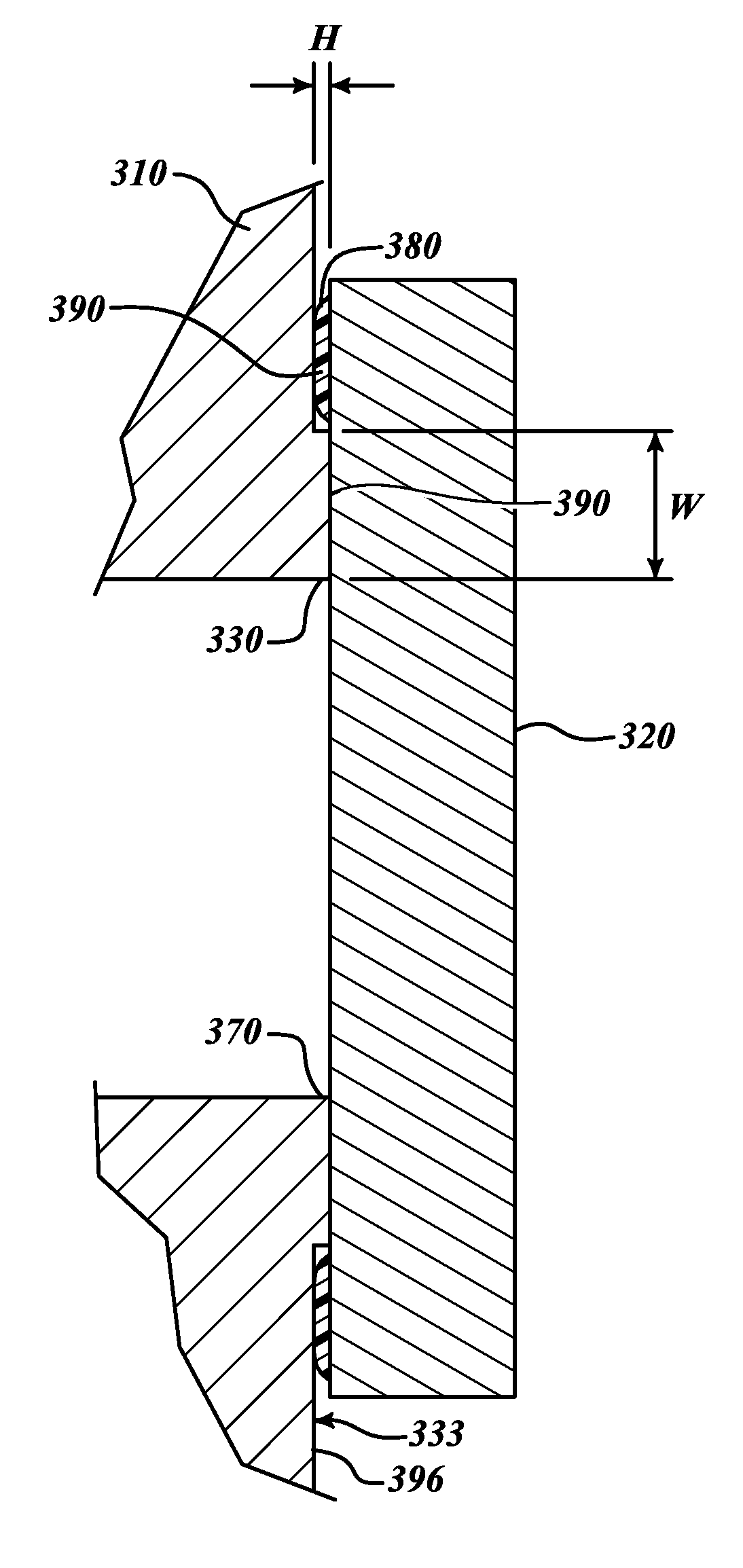
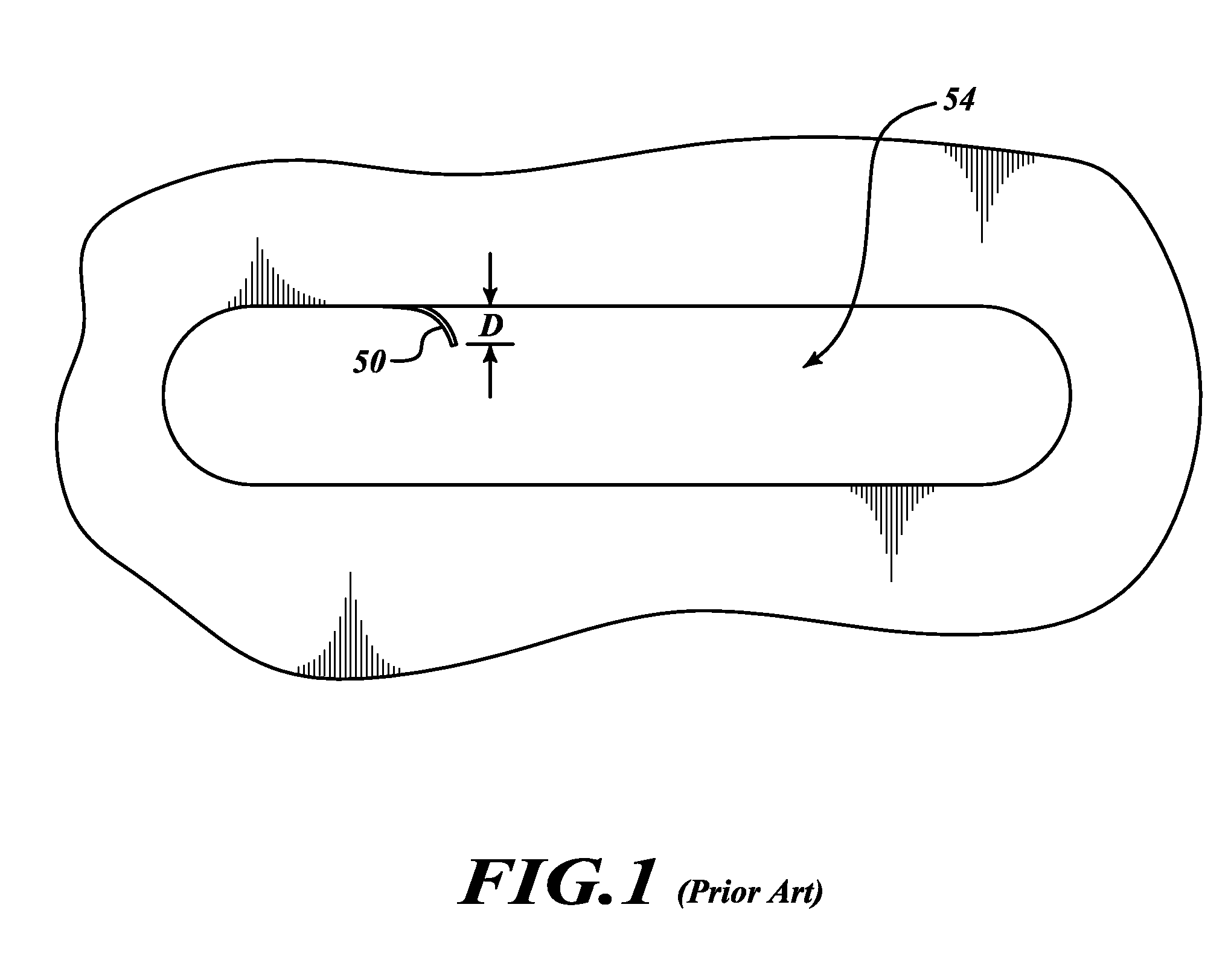
[0028]The entrance 140 includes a door tunnel 154 that can remain unobstructed and generally stringer free for a much longer time than conventional door tunnels to reduce the frequency of cleaning operations, reduce yield losses, and allow the use of large substrate handlers. Solid material build-up within the tunnel 154 can be ...


PUM

PropertyMeasurementUnit
depthaaaaaaaaaa
depthaaaaaaaaaa
distanceaaaaaaaaaa

Abstract

A substrate processing apparatus includes an enclosure defining a reaction chamber, a substrate holder in the reaction chamber, and a door assembly. The door assembly has a substrate entrance with a tunnel extending to the reaction chamber, a door movable with respect to the substrate entrance, and a pattern of features. The features are located along a portion of the substrate entrance defining the tunnel. The features promote sticking of processing byproducts, produced in the reaction chamber, to the substrate entrance. A door mates with the entrance to form a seal that reduces flow through the tunnel to control the amount of byproducts that enter the tunnel.

Description

CROSS-REFERENCE TO RELATED APPLICATION[0001]This application claims the benefit under 35 U.S.C. §119(e) of U.S. Provisional Patent Application No. 61 / 142,121 filed Dec. 31, 2008, which is incorporated herein by reference in its entirety.BACKGROUND[0002]1. Technical Field[0003]This invention relates to substrate processing chambers and, in particular, to door assemblies for controlling the formation of deposits within tunnels of the door assemblies.[0004]2. Description of the Related Art[0005]Wafer etching processes performed within conventional processing chambers often result in the accumulation of etch byproducts on walls of the processing chambers, as well as on other exposed components. Accumulated byproducts can impair processing quality and can reduce overall processing efficiency, thereby leading to reduced throughput. For example, solid polymer byproducts often form deposits at the tops of door tunnels. These deposits tend to peel and form flakes. Additional polymer byproduc...

Claims


Application Information

Patent Timeline
Patent Type & Authority Patents(United States)
IPC IPC(8): H01L21/306H01L21/67F16K3/02C23F1/08
CPCC23F1/08F16K3/0218H01L21/67126
Inventor BROEKER, JUSTIN
Owner STMICROELECTRONICS SRL
Why Eureka
Try Eureka