Multi-channel flow control valve

A flow regulating valve and multi-channel technology, which is applied to fluid distribution valves, valve details, valve devices, etc., can solve the problems of inconvenient operation of flow regulating valves, increased adjustment accuracy errors, and increased costs, and achieve rapid flow regulation operations , Increase the number of gears, reduce the effect of vibration

Active Publication Date: 2016-11-23
山东美迪宇能医疗科技有限公司
View PDF5 Cites 0 Cited by
  • Summary
  • Abstract
  • Description
  • Claims
  • Application Information

AI Technical Summary

Problems solved by technology

There are many defects in the existing flow control valve: when the flow demand needs to be switched between several values, the operation of the existing flow control valve is not convenient enough; in the case of long-term or frequent switching, the adjustment accuracy of the existing flow control valve will be reduced. The error increases with the wear of the parts; under high pressure, it is easy to produce erosion and cavitation, which will cause different degrees of damage to the valve core; when used in conjunction with a digital flowmeter, although the adjustment accuracy can be guaranteed, it will be greatly increase the cost

Method used


Image

  • Multi-channel flow control valve
  • Multi-channel flow control valve
  • Multi-channel flow control valve

Examples


Embodiment Construction

[0018] The present invention will be further described below in conjunction with accompanying drawing by non-limiting embodiment:

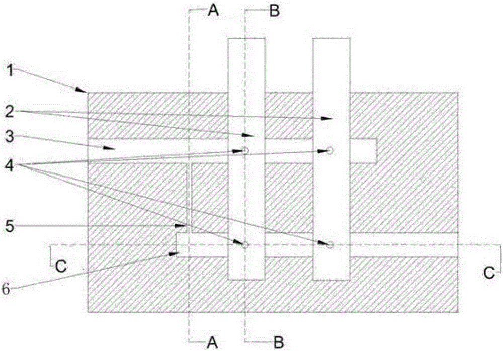
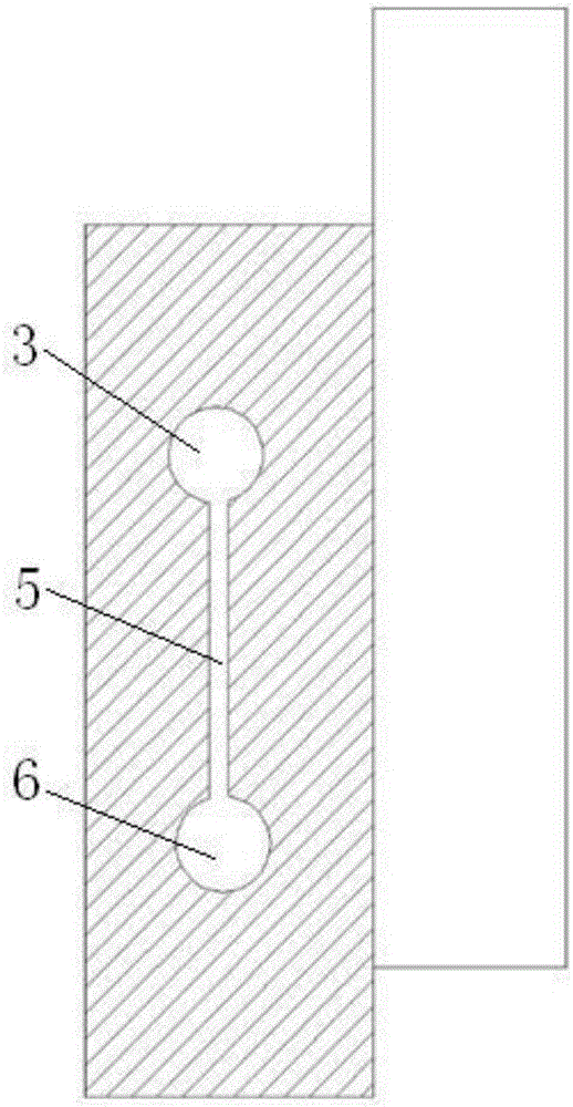
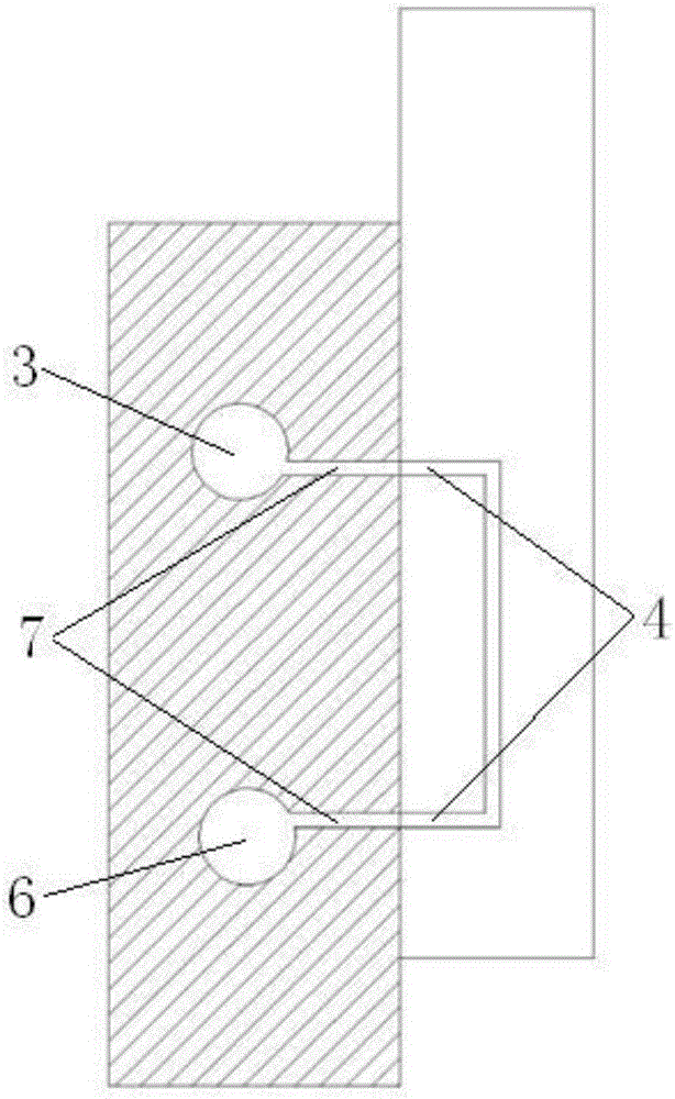
[0019] As shown in the drawings, a multi-channel flow regulating valve includes a valve body 1 and a plurality of solenoid valves 2 installed on the valve body 1 . In this embodiment, two solenoid valves 2 are installed on the valve body 1 . The valve body 1 is provided with a main input passage 3 and a main output passage 6 arranged parallel to each other. One end of the main input passage 3 runs through the valve body 1 as a fluid inlet, and the other end does not pass through the valve body 1. The main output passage 6 One end goes through the valve body 1 to serve as a fluid outlet, and the other end does not go through the valve body 1 . The fluid inlet and the fluid outlet are respectively located at opposite ends of the valve body 1 . At one end of the main output passage 6 that does not pass through the valve body 1, a normally open passa...


PUM


Abstract

The invention discloses a multi-channel flow control valve. The multi-channel flow control valve comprises a valve body and a plurality of electromagnetic valves mounted on the valve body, wherein a main input channel and a main output channel which are parallel to each other are arranged in the valve body; one end of the main input channel penetrates through the valve body and is served as a fluid inlet, and the other end does not penetrate through the valve body; one end of the main output channel penetrates through the valve body and is served as a fluid outlet, and the other end does not penetrate through the valve body; the fluid inlet and the fluid outlet are respectively positioned at the two opposite ends of the valve body; a normal-open channel is arranged at the end, which does not penetrate through the valve body, of the main output channel and communicates with the main input channel; a plurality of by-pass flow holes communicating with the main input channel and the main output channel are formed in the axial directions of the main input channel and the main output channel respectively; the by-pass flow holes in the main input channel and the main output channel are distributed in a one-to-one correspondence manner; an electromagnetic valve is mounted corresponding to each pair of the by-pass flow holes; two flow holes corresponding to such pair of the by-pass flow holes respectively are formed in the electromagnetic valve; and the two flow holes in the electromagnetic valve communicate with each other.

Description

technical field [0001] The invention relates to a flow regulating valve, which belongs to the technical field of valves. Background technique [0002] In the prior art, the flow regulating valve adopts a single valve body, and the flow of the fluid is linearly adjusted by adjusting the opening of the valve plate. There are many defects in the existing flow control valve: when the flow demand needs to be switched between several values, the operation of the existing flow control valve is not convenient enough; in the case of long-term or frequent switching, the adjustment accuracy of the existing flow control valve will be reduced. The error increases with the wear of the parts; under high pressure, it is easy to produce erosion and cavitation, which will cause different degrees of damage to the valve core; when used in conjunction with a digital flowmeter, although the adjustment accuracy can be guaranteed, it will be substantially increase costs. Contents of the inventio...

Claims


Application Information

Patent Timeline
Patent Type & Authority Applications(China)
IPC IPC(8): F16K21/02F16K27/00
CPCF16K21/02F16K27/00
Inventor 冯凯吴洪刚原铮崔粤
Owner 山东美迪宇能医疗科技有限公司
Why Eureka
Try Eureka