Sensing of a magnetic target

A technology for magnetic targets and targets, which is applied in the field of magnetic target sensing and can solve problems such as positioning errors

Active Publication Date: 2016-11-23
THE BOEING CO
View PDF7 Cites 5 Cited by
  • Summary
  • Abstract
  • Description
  • Claims
  • Application Information

AI Technical Summary

Problems solved by technology

Positioning errors can result as the array will appea...

Method used


Image

  • Sensing of a magnetic target
  • Sensing of a magnetic target
  • Sensing of a magnetic target

Examples


Embodiment Construction

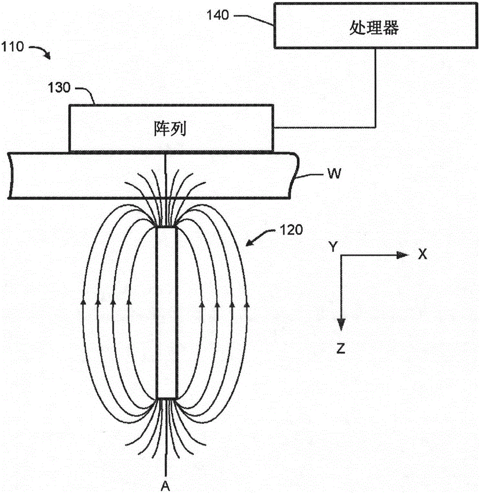
[0018] refer to figure 1 , which illustrates an apparatus 110 comprising a magnetic target 120 for generating a magnetic field that is fairly uniform and concentric about its central axis (A). Flux lines radiate outward from the magnetic target 120 .

[0019] The magnetic target 120 defines a global X-axis, Y-axis, and Z-axis that form a global coordinate system. The Z axis coincides with the central axis (A) of the magnetic target 120, and a global X-Y plane is formed by the X and Y axes. The global X-Y plane is perpendicular to the central axis (A). The flux lines are assumed to be straight considering that the magnetic field is fairly uniform and concentric when viewed in the global X-Y plane.

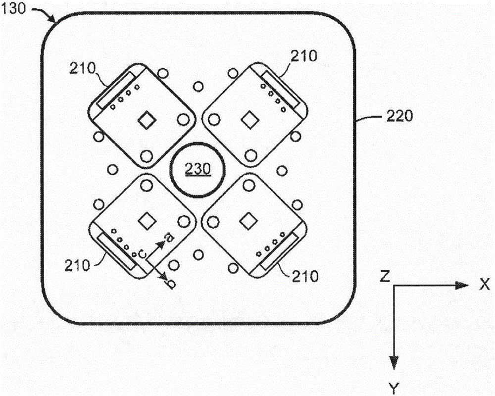
[0020] The device 110 further includes an array 130 of three-axis digital magnetic compasses for sensing magnetic fields. Each digital magnetic compass senses the magnetic field along its local a, b, and c axes, which form a local coordinate system. For example, each digital ma...


PUM


Abstract

The present invention relates to the sensing of a magnetic target. The apparatus (110) comprises a magnetic target (120) for generating a magnetic field that is uniform and concentric about a central axis of the target (120); an array (140) of three-axis digital magnetic compasses (210) for sensing the magnetic field; and a processor for finding intersection points of vectors from the compasses to the target (120). The vectors lie in a global X-Y plane that is normal to the central axis. Each vector indicates a direction of sensed magnetic field from one of the compasses to the magnetic target (120).

Description

Background technique [0001] Magnetic targets and sensor arrays can be used to locate hidden features behind non-magnetic walls. A magnetic target is placed at a feature behind the wall and the sensor array is scanned across the front surface of the wall. The flux lines from the magnetic target are sensed by the sensor array. [0002] Each sensor of the array can use the absolute field strength as a measure of the position of the magnetic field. The relative position of the magnetic target can be inferred by determining the difference in measured magnetic field strength between different sensor pairs and using this difference to triangulate the relative position of the magnetic target. [0003] In general, the difference in field strength sensed is proportional to the distance of the array to the magnetic target, but not always. If the magnetic target produces a weak field, or if both sensors in a pair are far away from the magnetic target, then the difference appears weaker...

Claims


Application Information

Patent Timeline
IPC IPC(8): G01B7/00
CPCG01B7/004G01V3/081G01V15/00G01R33/0094G01R33/0206G01R33/12G01R33/0005G01R33/0029G01C17/02G01R1/16G01C17/28G01D5/16H01F7/0278
Inventor S·J·菲伊拉A·R·默克雷
Owner THE BOEING CO
Why Eureka
Try Eureka