Pool cleaning robot

a cleaning robot and pool technology, applied in the direction of navigation instruments, instruments, separation processes, etc., can solve the problems of noticeable deviation from the intended scanning path, and the inability to realize the ideal straight path of the robot,

Inactive Publication Date: 2009-03-05
MAYTRONICS
View PDF7 Cites 111 Cited by
  • Summary
  • Abstract
  • Description
  • Claims
  • Application Information

AI Technical Summary

Benefits of technology

[0019]At least one of the setup parameters may be selected from the group comprising one or more of dimensions of the pool, cycle time, delay until cycle start, scanning method, whether to log scanning data, and pool shape.
[0020]The control system may be adapted to store multiple sets of setup parameters for multiple pools, to store scanning data, and/or to store the scanning information on removable media.
[0021]Th

Problems solved by technology

However, due to a number of conditions, including, but not limited to, shifting of the robots due to movement of the water, slippage of the drive belts along the floor, bumps and/or depressions in the floor of the pool, etc., this ideal straight path is often not realized by the

Method used


Image

  • Pool cleaning robot
  • Pool cleaning robot
  • Pool cleaning robot

Examples


Embodiment Construction

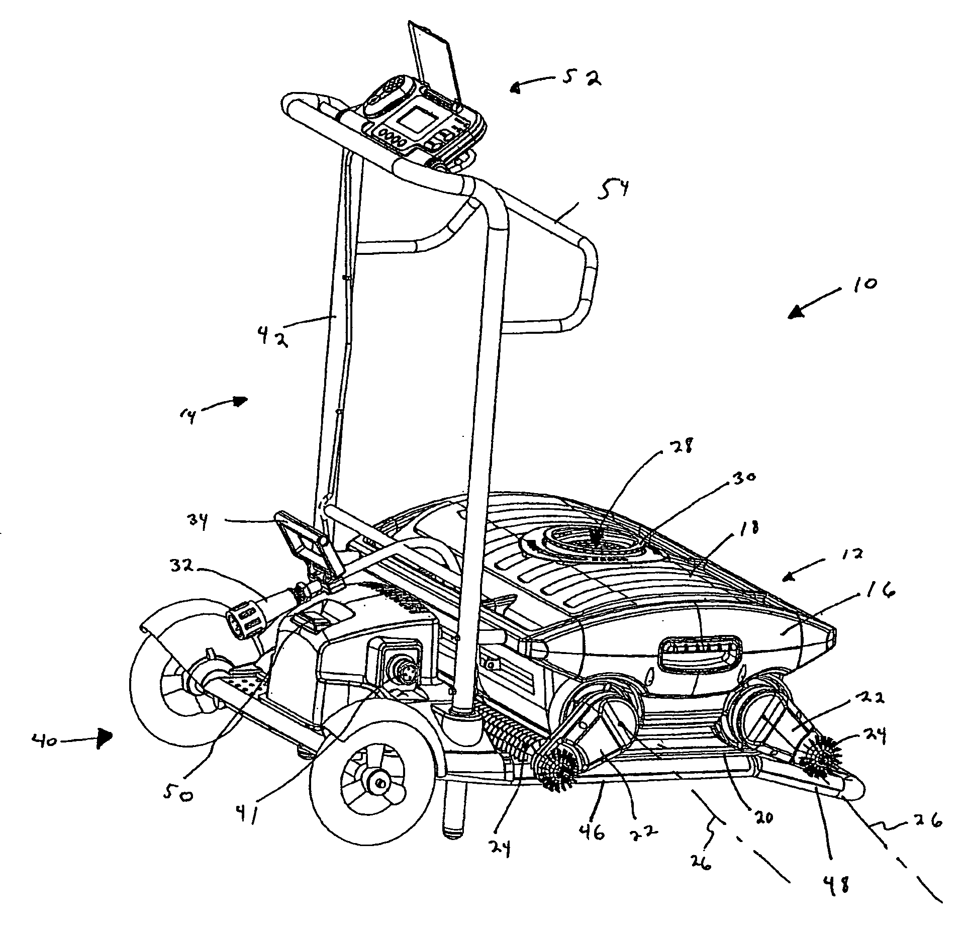
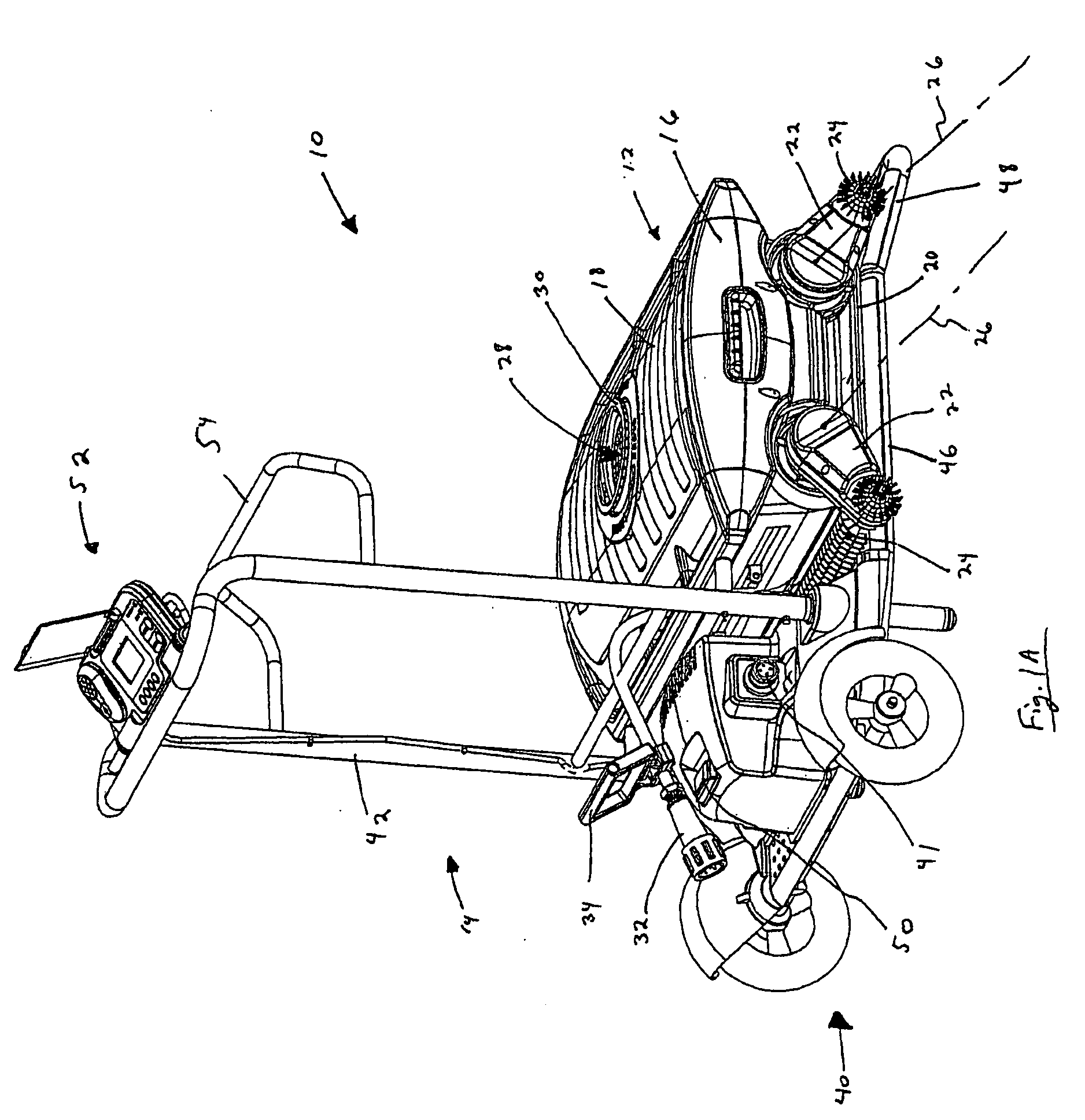
[0058]As illustrated in FIG. 1A, there is provided one example of a pool cleaning system, according to the present invention, which is generally indicated at 10. The pool cleaning system 10 comprises a pool cleaning robot 12 and a caddy 14.

[0059]The robot 12 comprises a main housing 16, a removable cover 18, which provides access to the interior of the main housing from the top of the robot, an internal motor unit (not seen) mounted within the main housing, a drive belt 20 driven by the motor unit, and two pairs of pivotable arms 22, each pair supporting an active brush 24 (only one pivotable arm 22 of each of the pairs is visible in FIG. 1A). Each pair of pivotable arms 22 and its respective brush 24 is adapted to pivot about an axis 26. The bottom of the robot 12 comprises one or more inlets (not seen), and the cover 18 comprises an outlet 28. One or more filters (not seen), which may be disposable, are provided within the main housing 16, in the fluid path between the inlet(s) an...


PUM

PropertyMeasurementUnit
Angleaaaaaaaaaa
Lengthaaaaaaaaaa
Timeaaaaaaaaaa

Abstract

A pool cleaning robot adapted to move in a direction along the bottom surface of a pool. The robot comprises a compass, a rate gyroscope, and a controller adapted to determine the orientation of the robot, relative to a reference orientation thereof, based on readings of the compass and the gyroscope.

Description

FIELD OF THE INVENTION[0001]This invention relates to devices and methods for cleaning swimming pools, basins, and the like. More particularly, the invention relates to an automatic self-propelled cleaning robot.BACKGROUND OF THE INVENTION[0002]Pool cleaning robots, that is, robot-like devices which automatically scan along, typically, at least the bottom surface of a pool or other similar liquid-filled basin, are known in the art. Typically, a pool cleaning robot comprises locomotion means, such as wheels or track-belts, an inlet, and outlet, and suction means to move water into the body of the robot via the inlet and expel it via the outlet, and a filter to clean the water as it passes through the body of the robot between the inlet and the outlet. The robots may be corded or cordless, i.e., battery powered.[0003]In addition, the robot may comprise a robot controller adapted to direct the motion of the robot according to one or more preprogrammed algorithms. During normal operatio...

Claims


Application Information

Patent Timeline
IPC IPC(8): B01D21/30B01D35/02C02F1/00G01C21/20
CPCE04H4/1654G05D2201/0203G05D1/027
Inventor GARTI, EFRAIM
Owner MAYTRONICS
Why Eureka
Try Eureka