Reaction kettle leakage detection device

A detection device and reaction kettle technology, which is applied in the direction of measuring the increase and decrease rate of the fluid, using liquid/vacuum degree to measure the liquid tightness, etc., can solve the problem of inability to accurately detect the leakage position of the device, time-consuming and laborious operation, and small detection position and other problems, to save operating time, ensure stability, and facilitate disassembly and fixation

Inactive Publication Date: 2016-11-23
南京通用化工设备技术研究院
View PDF6 Cites 4 Cited by
  • Summary
  • Abstract
  • Description
  • Claims
  • Application Information

AI Technical Summary

Problems solved by technology

[0003] Reactor leakage generally occurs at the connection position of the reactor. Due to the limitation of its structure, ordinary detection devices can only detect reactors of specific materials. In the process of detection and judgment, large-scale detection equipment can detect large The fault condition of the equipment wit

Method used


Image

  • Reaction kettle leakage detection device
  • Reaction kettle leakage detection device

Examples


Example Embodiment

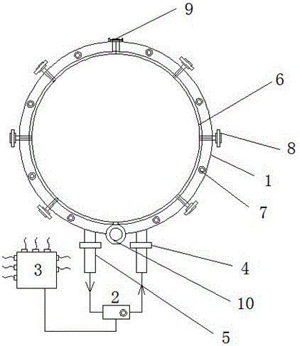
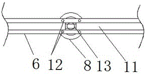
[0015] Embodiment 1: as figure 1 and 2 A reaction kettle leakage detection device is shown, the detection device is set on the shell of the reaction kettle, and the detection device includes: a ring detector 1, a circulating pressure water pump 2 and a control panel 3, the described The ring detector 1 is a ring-shaped shell, and the inside of the shell 1 is provided with a pressure water channel 11. The pressure water channel 11 is a pipe with a C-shaped cross section, and the inner side of the pressure water channel 11 is directly attached to the reactor. On the shell, the inner side of the shell 1 is provided with a ring-shaped sealing layer 6, the sealing layer 6 is set on the upper and lower sides of the pressure water channel 11, and the shell 1 is provided with a water inlet pipe 4 and a water outlet pipe 5, the said The water inlet pipe 4 and the water outlet pipe 5 are all connected to the circulating pressure water pump 2, and a plurality of pressure detection probe...

Example Embodiment

[0016] Embodiment 2: as figure 1 and 2 As shown, the ring detector housing 1 is composed of two semicircular pipes of the same size, one end of the two semicircular pipes is connected to each other through a rotating shaft 10, and one end is connected to each other through a lock nut 9; The ring detector housing 1 installed in combination facilitates the disassembly and fixing of the ring detector and saves the operating time of the detection work.

Example Embodiment

[0017] Embodiment 3: as figure 1 and 2 As shown, the water inlet pipe 4 and the water outlet pipe 5 are respectively connected to two semicircular pipes; during the detection process of this device, water with a certain pressure is passed into the ring detector 1 to ensure that the overall detector 1 The water pressure at each position is uniform, and the water flow must pass into one end of the two semicircular pipes and discharge from the other end to complete the uniform control of the pressure.


PUM


Abstract

The invention discloses a reaction kettle leakage detection device which comprises an annular detector, a circulation pressure water pump and a control panel. The annular detector is an annular shell. A pressure water channel is arranged inside the shell. The cross section of the pressure water channel is in a C shape. The inner side of the pressure water channel is directly attached to the shell of a reaction kettle. Annular sealing layers are arranged on the inner side of the shell. The sealing layers are arranged on the upper side and the lower side of the pressure water channel. A water inlet pipe and a water outlet pipe are arranged on the shell and connected to the circulation pressure water pump. A plurality of pressure detection probes are evenly distributed on the shell. The shell of the reaction kettle is sleeved with the device, shell bodies on the same height position on the shell of the reaction kettle can be detected by the device body within the same time, and the leakage position of the reaction kettle is precisely determined on the basis of data reflected by the control panel and the pressure detection probe; the working efficiency of the reaction kettle leakage detection work is improved.

Description

technical field [0001] The invention relates to the field of detection equipment for pressure vessels, in particular to a leakage detection device for a reaction kettle. Background technique [0002] In view of the diversity of the chemical reaction itself, according to the different types of reactants, there are many kinds of reactor materials on the market at present. After working for a long time, different reactors need to be tested for safety. Therefore, during the testing process Corresponding detection devices are required, and different detection devices are used for detection according to different types of reactors. [0003] Reactor leakage generally occurs at the connection position of the reactor. Due to the limitation of its structure, ordinary detection devices can only detect reactors of specific materials. In the process of detection and judgment, large-scale detection equipment can detect large The fault condition of the equipment within the range, but the ...

Claims


Application Information

Patent Timeline
IPC IPC(8): G01M3/32
CPCG01M3/32
Inventor 胡家富张耀丰刘晓利
Owner 南京通用化工设备技术研究院
Why Eureka
Try Eureka