Balance spring pushing device

A technology of pushing device and hairspring, which is applied to supporting instruments, instruments, clocks and other directions of clocks, can solve problems such as roughness and small transfer capacity, and achieve the effects of small vibration, reduced vibration and reduced wear and tear.

Inactive Publication Date: 2016-11-23
SUZHOU TIANCHENGCHUANGDA ELECTRONICS CO LTD
6 Cites 0 Cited by

AI-Extracted Technical Summary

Problems solved by technology

After the hairspring is produced, it needs to be assembled precisely. During the assembly process, the cooperation of various staff is required, and the hairspring needs to be transfe...

Method used

[0021] The hairspring pushing device of the present invention is provided with a slide assembly 2 for placing the hairspring and for short-distance transmission of the hairspring. When transmitting, the hairspring is placed on the moving plate 24 on the slide assembly 2, and the moving plate 24 is used to move the hairspring on the guide rail 23 The balance spring is transferred by moving horizontally on the top. This transfer method is very stable, and the vibration is small during the transfer process, which satisfies the transmission of precision small parts. The push assembly 3 provided on the upper part of the slide assembly 2 is used to push the movement The plate 24 is transferred, and the push assembly 3 is gently driven by th...

Abstract

The invention discloses a balance spring pushing device which comprises a workbench, wherein a sliding plate component is arranged on the workbench and is used for loading a balance spring and transmitting the balance spring for a short distance; in a transmission process, the balance spring is put on a moving plate on the sliding plate component; the balance spring is transferred and loaded by horizontally moving the moving plate on a guide rail. The transferring loading manner is stable and firm; the vibration is small in the transferring loading process; the transmission of precise small parts is met; a pushing component arranged on the upper part of the sliding plate component is used for driving the moving plate to transfer and load; the pushing component is slowly driven by a stepping motor, so that the moving plate is moved at constant speed in a moving process and is stable and firm; buffering components arranged at the two ends between the slide rails have a buffering function and are used for buffering and damping the moving plate when the moving plate reciprocates to a terminal point and is about to stop; the vibration is reduced when the moving plate is stopped; the vibration of the balance spring in the moving plate is reduced; the abrasion of the balance spring is reduced.

Application Domain

Clock support devices

Technology Topic

Image

  • Balance spring pushing device
  • Balance spring pushing device
  • Balance spring pushing device

Examples

  • Experimental program(1)

Example Embodiment

[0014] In order to make it easy to understand the technical means, creative features, objectives and effects achieved by the present invention, the present invention will be further described with reference to specific embodiments below.
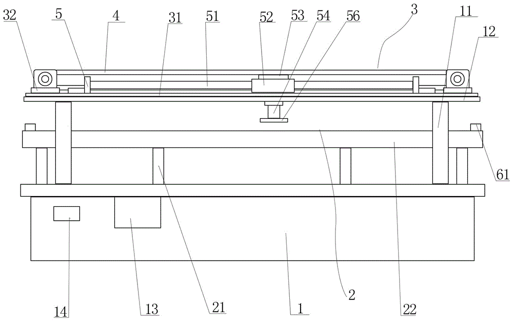
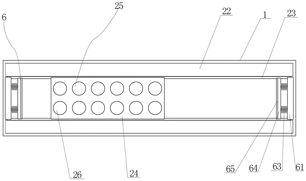
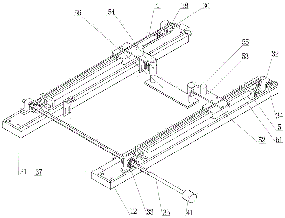
[0015] Such as Figure 1 to Figure 3 As shown, a hairspring pushing device of the present invention includes a workbench 1 on which a slide assembly 2 is provided. The feature is that the slide assembly 2 includes two rows of corresponding support rods 21 provided on the workbench 1. , The support rods 21 are all vertically arranged, each row of support rods 21 is provided with a slide 22 at the top, two slides 22 are arranged in parallel, the adjacent inner side of the slide 22 is provided with a guide rail 23, there is a connection between the two guide rails 23 The moving plate 24, which can reciprocate on the guide rail 23, is provided with buffer assemblies 6 at both ends between the slideways 22, and the buffer assembly 6 includes a support plate 61 connecting the two slideways 22, one side of the support plate 61 There are two grooves, both of which are horizontally provided with a high-pressure spring 63, one end of the high-pressure spring 63 is vertically provided with a receiving plate 64, one end of the receiving plate 64 is provided with an elastic layer 65, and the movable plate 24 is provided with a balance spring The storage group 25 includes a number of circular storage slots 26 arranged in a matrix. The outer sides of the two rows of support rods 21 are provided with two support columns 11, and the top of each row of support columns 11 are horizontally connected to a horizontal plate 12, two A pushing assembly 3 is provided on the horizontal plate 12. The pushing assembly 3 includes a fixed plate 31 respectively arranged on the top of the two horizontal plates 12. Both ends of the fixed plate 31 are provided with a seat 32. The two supports 32 are respectively provided with A bearing 33 and a second bearing 34, a first roller shaft 35 is connected between the two corresponding first bearings 33, a second roller shaft 36 is connected to the two second bearings 34, both ends of the first roller shaft 35 A first pinion gear 37 is sleeved, and the two ends of the second roller shaft 36 are sleeved with a second pinion gear 38. A belt loop 4 is connected between the first pinion gear 37 and the second pinion gear 38. The two belt loops 4 are It is arranged in parallel, two fixing seats 5 are arranged between the supports 32, two parallel rods 51 are connected to the fixing seat 5, and a through groove for the belt loop 4 is opened in the middle of the fixing seat 5. The belt loop 4 It is arranged between two round rods 51. The round rod 51 is connected with a movable seat 52 that can reciprocate with the round rod 51. The movable seat 52 is connected to the belt loop 4. A connecting plate 53 is provided on the top of the movable seat 52 on both sides. A telescopic rod 54 is vertically arranged at one end of 53, and a pushing plate 56 is horizontally connected between the two telescopic rods 54, and the pushing plate 56 is arranged on the upper part of the moving plate 24.
[0016] In a preferred embodiment of the present invention, a buffer layer is provided on both sides of the pushing plate 56.
[0017] In a preferred embodiment of the present invention, a controller 13 is provided in the workbench 1, and a control panel 14 is provided on the side of the workbench 1.
[0018] In a preferred embodiment of the present invention, a ceramic layer is provided at the bottom of the storage tank 26.
[0019] In a preferred embodiment of the present invention, an air pump 55 is provided on the horizontal plate 12, and the air pump 55 is connected to a corresponding telescopic rod 54.
[0020] In a preferred embodiment of the present invention, one end of the first roller shaft 35 is provided with a stepping motor 41 that drives the first roller shaft 35 to rotate.
[0021] The hairspring pushing device of the present invention is provided with a sliding plate assembly 2 for placing the hairspring and for short-distance transmission of the hairspring. During transmission, the hairspring is placed on the moving plate 24 on the sliding plate assembly 2, and the horizontal movement of the moving plate 24 on the guide rail 23 is used. The balance spring is transferred by moving. This transfer method is very stable, and the vibration is small during the transfer process, which satisfies the transmission of precision small parts. The push assembly 3 set on the upper part of the slide assembly 2 is used to push the moving plate 24 For transfer, the pushing assembly 3 is gently driven by the stepping motor 41 to keep the moving plate 24 moving at a constant speed, which is very stable. The storage group 25 set on the moving plate 24 is provided with multiple storage slots 26 to place the hairspring. Multiple hairsprings can be transferred, which is convenient and efficient; the buffer components 6 set at both ends between the slide rails 22 play a buffering role, and are used to give the moving plate 24 a buffer reduction when the reciprocating movement reaches the end point and is about to stop. The effect of vibration reduces the vibration when the moving plate 24 stops, and at the same time reduces the vibration of the hairspring in the moving plate 24, reducing the wear of the hairspring.
[0022] The support rod 21 included in the skateboard assembly 2 is provided with two rows for connecting the slideways 22, and the two rows of support rods 21 are provided with two slideways 22. The two slideways 22 are arranged in parallel to facilitate the placement and movement of the movable plate 24. The guide rail 23 provided on the inner side of the road 22 is used to connect the moving plate 24, and the buffer assembly 6 is provided at both ends of the slide rail 22. The buffer assembly 6 includes a support plate 61 for connecting the high-pressure spring 63. One end of the high-pressure spring 63 is provided for receiving The plate 64 is used to receive the vibration from the moving plate 24. The elastic layer 65 provided at one end of the receiving plate 64 further reduces the vibration. The storage group 25 provided on the moving plate 24 is used to place the hairspring. The storage group 25 includes a matrix arranged in a circle. The present embodiment is provided with two rows of storage grooves 26. When the bottom of the storage groove 26 is provided with a ceramic layer, the hairspring is kept clean and not contaminated during placement and transfer.
[0023] The pushing assembly 3 is arranged on the horizontal plate 12. The pushing assembly 3 includes a fixed plate 31 arranged on the top of the horizontal plate 12. Two ends of the fixed plate 31 are provided with supports 32, and the two supports 32 are respectively provided with first bearings 33 and the second bearing 34, the first roller shaft 35 is connected between the two first bearings 33, the first roller shaft 35 can freely rotate, the two second bearings 34 are respectively connected with the second roller shaft 36, The roller shaft 36 can rotate freely. A first pinion gear 37 is sleeved on both ends of the first roller shaft 35, and a second pinion gear 38 is sleeved on both ends of the second roller shaft 36. The first pinion gear 37 is connected to the second pinion gear. A belt loop 4 is connected between the gears 38. A stepping motor 41 provided at one end of the first roller shaft 35 is used to drive the first roller shaft 35 to rotate. The first roller shaft 35 rotates to drive the first pinion gear 37 to rotate, thereby driving the belt The ring 4 rotates. The two fixed seats 5 provided between the supports 32 are used to connect the round rod 51. The movable seat 52 provided on the round rod 51 can move back and forth with the round rod 51. The movable seat 52 is connected to the belt ring 4, and the belt The ring 4 is driven by the stepping motor 41 to rotate to drive the moving base 52 to move back and forth. The moving base 52 is connected to a push plate 56 through a connecting plate 53 and a telescopic rod 54. The push plate 56 is used to push the moving plate 24 back and forth to transfer the hairspring. .
[0024] In actual operation, the worker puts the hairspring in the storage slot 26, and then the telescopic rod 54 moves down to drive the pushing plate 56 down to the side of the moving plate 24, and the stepping motor 41 rotates to drive the belt loop 4 to rotate, thereby driving the push The plate 56 moves, and the pushing plate 56 pushes the moving plate 24 to move. The moving plate 24 is moved smoothly on the guide rail 23 to achieve the purpose of transferring the hairspring. After the transfer is completed, the pushing plate 56 rises and then moves to the other end of the moving plate 24. Move and reset the empty moving plate 24 to complete the work.
[0025] Both sides of the pushing plate 56 are provided with a buffer layer to slow down the vibration generated during pushing. The controller 13 provided in the workbench 1 is used to control the operation of the equipment, and the control panel 14 is used for manual regulation.
[0026] The above embodiment is only one of the embodiments of the present invention, and its description is relatively specific and detailed, but it should not be understood as a limitation to the scope of the present invention. It should be pointed out that for those of ordinary skill in the art, without departing from the concept of the present invention, several modifications and improvements can be made, and these all fall within the protection scope of the present invention. Therefore, the protection scope of the patent of the present invention should be subject to the appended claims.

PUM

no PUM

Description & Claims & Application Information

We can also present the details of the Description, Claims and Application information to help users get a comprehensive understanding of the technical details of the patent, such as background art, summary of invention, brief description of drawings, description of embodiments, and other original content. On the other hand, users can also determine the specific scope of protection of the technology through the list of claims; as well as understand the changes in the life cycle of the technology with the presentation of the patent timeline. Login to view more.

Similar technology patents

Parking lock device

Owner:TOYOTA JIDOSHA KK

Internal motorized bicycle hub

ActiveUS20120161495A1Reduce vibrationEasily propagatedAssociation with control/drive circuitsElectric devicesMotorized bicycleStator
Owner:SHIMANO INC

Turbocharger control linkage with reduced heat flow

InactiveUS20130011243A1Increase control linkage shaft stiffnessReduce vibrationConnecting rodsInternal combustion piston enginesHeat sinkHeat flow
Owner:BORG WARNER INC

Classification and recommendation of technical efficacy words

  • Reduce vibration
  • Convenience and efficiency

Airing equipment for linen and cotton primary processing

InactiveCN107560365AGood air drying effectConvenience and efficiencyDrying gas arrangementsDrying machines with non-progressive movementsEngineeringAir drying
Owner:南京极佳物联网科技有限公司

Light curing 3D printing preparing method for complex double-wall silicon-based ceramic core

ActiveCN111098387AConvenience and efficiencyReduce process stepsAuxillary shaping apparatusInvestment castingStl file
Owner:INST OF METAL RESEARCH - CHINESE ACAD OF SCI

Coal mine underground positioning dust removal system

PendingCN112554949AIntelligent operationConvenience and efficiencyMining devicesDust removalCoalMining engineering
Owner:TAIYUAN UNIV OF TECH
Why Eureka
Try Eureka