Switching device, terminal and terminal heat dissipation method

A switch device and terminal technology, which is applied in the field of communication, can solve the problems of poor user experience and high temperature, and achieve the effect of lowering the temperature, good heat dissipation effect, and realizing heat dissipation

Inactive Publication Date: 2016-11-23
ZTE CORP
View PDF0 Cites 11 Cited by
  • Summary
  • Abstract
  • Description
  • Claims
  • Application Information

AI Technical Summary

Problems solved by technology

Some areas of the mobile phone generate a certain amount of heat in specific scenarios. During actual use, users will encounter these areas with relatively large heat generation just in the part where the hand is held for a long time, which will cause the hand to hold for a long time. The temperature of the part is high, resulting in poor user experience

Method used


Image

  • Switching device, terminal and terminal heat dissipation method
  • Switching device, terminal and terminal heat dissipation method
  • Switching device, terminal and terminal heat dissipation method

Examples


Embodiment Construction

[0035] The technical solutions of the present invention will be further described below in conjunction with the drawings and specific embodiments. It should be understood that the specific embodiments described here are only used to explain the present invention and are not intended to limit the present invention.

[0036] The invention provides a switch device, a terminal and a heat dissipation method for the terminal.

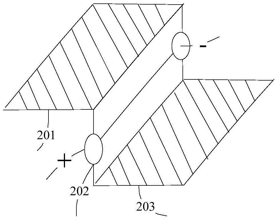
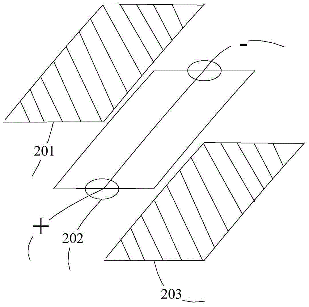
[0037] refer to figure 1 , figure 2 shown, figure 1 It is a schematic diagram of a closed state of a preferred embodiment of the switch device of the present invention, figure 2 It is a schematic diagram of the disconnected state of a preferred embodiment of the switching device of the present invention; the switching device of this embodiment includes a first heat dissipation conductor 201, a connecting structure 202 and a second heat dissipation conductor 203. The first heat dissipation conductor 201 and the second heat dissipation conductor 203 are com...


PUM


Abstract

The invention discloses a switching device, a terminal and a terminal heat dissipation method. The switching device comprises a first heat dissipation conductor, a second heat dissipation conductor and a connecting structure arranged between the heat dissipation conductors, wherein the connecting structure is used for realizing disconnection and connection of the first heat dissipation conductor and the second heat dissipation conductor. The terminal comprises a holding part detection device, a temperature detection device arranged in a terminal heat source area, the switching device, a processor device and multiple heat dissipation devices distributed in a heat source area and a non-heat-source area of the terminal, and the switching device is arranged between the heat source area and the non-heat-source area of the terminal. With the adoption of the terminal, heat in the heat source area held by a user is dissipated to an area which is not held by the user in the non-heat-source area, and good use experience is provided for the user.

Description

technical field [0001] The invention relates to the communication field, in particular to a switch device, a terminal and a terminal heat dissipation method. Background technique [0002] Existing mobile phones, especially smart phones, have become very important communication, entertainment, and office tools in people's daily life. As a result, the heat of the mobile phone is getting higher and higher. If the heat of the mobile phone cannot be dissipated in time, the performance of the whole machine will be affected. The overheating of the mobile phone will lead to poor subjective experience of the user. At present, the most commonly used heat dissipation method is to use heat-conducting materials on the main heat-generating components such as the main chip, power amplifier, and power management to conduct heat to the mobile phone shell and then dissipate it through the shell. Some areas of the mobile phone generate a certain amount of heat in specific scenarios. During ac...

Claims


Application Information

Patent Timeline
Patent Type & Authority Applications(China)
IPC IPC(8): G06F1/20H04M1/02
CPCG06F1/20H05K7/20
Inventor 李春利
Owner ZTE CORP
Why Eureka
Try Eureka