Current transformer integrated device

A current transformer and integrated device technology, applied in the direction of inductors, transformers/inductor coils/windings/connections, voltage/current isolation, etc., can solve the problems of consuming land space, increasing the risk of electric shock, and many installation times, and achieve The effect of reducing installation and maintenance costs, improving construction safety, and improving the ability to prevent electricity theft

Inactive Publication Date: 2016-11-23
何排枝
View PDF5 Cites 1 Cited by
  • Summary
  • Abstract
  • Description
  • Claims
  • Application Information

AI Technical Summary

Problems solved by technology

[0003] Since the current transformer currently on the market is usually a single current transformer, there is only one input terminal and output terminal of the primary line, and the transformer is electrically connected to the primary line in series; in order to connect with a low-voltage meter to realize For metering, the main current circuit and current branch circuits in the power system need to be installed with current transformers respectively. On the one hand, this arrangement requires the installation of relevant equipment on the main circuit and each branch circuit separately. The number of installations is many, and it consumes manpower and material resources. , and increases the chance of contact with the primary outlet during construction, which increases the risk of electric shock; on the other hand, the number of access devices required is large, which also increases the access cost and consumes a lot of space
[0004] In addition, when electricity stealing occurs on a line, if it is necessary to analyze which branch circuit has electricity stealing, professionals need to use professional detection methods and go to the main road and branch road to read meters for comparison and detection, which is more complicated in operation

Method used


Image

  • Current transformer integrated device
  • Current transformer integrated device
  • Current transformer integrated device

Examples


Embodiment Construction

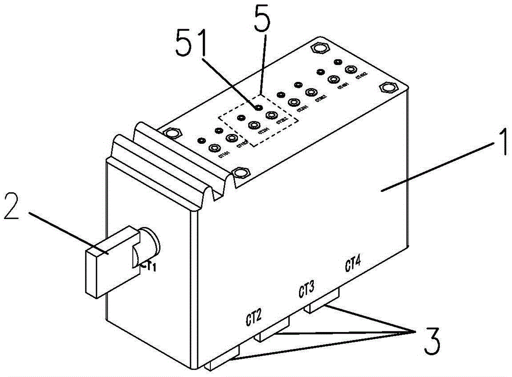
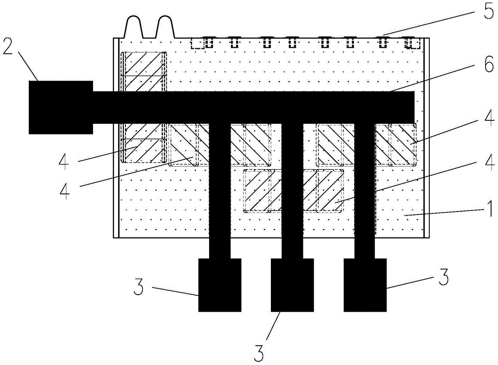
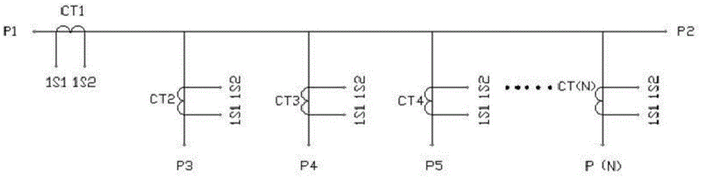
[0016] refer to figure 1 , figure 2 , image 3 , a current transformer integrated device, the current transformer integrated device includes an insulator 1 filled with insulating material, the insulator 1 is connected in series with a current transformer 4 to form a primary incoming line 2 and a plurality of current transformers 4 in parallel to form multiple One primary outlet 3; the current transformer 4 is electrically connected with multiple groups of secondary outlet terminals 5 provided on the insulator 1 in one-to-one correspondence.

[0017] When in use, the primary line is connected to the primary incoming line 2 in the insulator 1, the primary incoming line 2 is formed by a wire connected with a current transformer 4 in series, and then a plurality of current transformers 4 are connected in parallel to form a plurality of primary outgoing lines 3, and pass through The primary outgoing line 3 is connected to the user circuit, which avoids a lot of work caused by th...


PUM


Abstract

The invention discloses a current transformer integrated device, which comprises an insulation body filled with insulating materials. A current transformer is serially connected into the insulation body to form a primary inlet wire and a plurality of current transformers are connected into the insulation body in parallel to form a plurality of primary outlet wires; the current transformers are electrically connected with multiple groups of secondary outlet wire terminals arranged on the insulation body in a one-to-one correspondence way. According to the current transformer integrated device provided by the invention, single-input multiple-output of the current transformers is realized through integrated design, the installation of current transformers on a primary road and multiple branch roads is integrally realized, the manner of independently installing the single-input single-output current transformers on the primary rod and the multiple branch roads in the prior art is avoided, the installation and maintenance cost is reduced, the construction safety is improved, the equipment is simplified, and the land space is saved; meanwhile, through a single-input multiple-output integrated arrangement way, a measuring main meter and measuring submeters can be gathered together so as to directly monitor the electric quantity of each current circuit conveniently, the workload is greatly reduced, and the electricity larceny prevention of the circuits is improved.

Description

technical field [0001] The invention relates to a current transformer integration device. Background technique [0002] It is very dangerous to directly connect the low-voltage metering equipment to the high-voltage line when measuring current. In order to facilitate the measurement of the power delivered by the high-voltage circuit with a low-voltage instrument, it is necessary to convert the large current on the line into a small current through a current transformer. The primary coil side of the device is connected to the primary circuit, and the secondary coil side is connected to low-voltage measuring instruments, relay protection devices and other equipment. [0003] Since the current transformer currently on the market is usually a single current transformer, there is only one input terminal and output terminal of the primary line, and the transformer is electrically connected to the primary line in series; in order to connect with a low-voltage meter to realize For ...

Claims


Application Information

Patent Timeline
Patent Type & Authority Applications(China)
IPC IPC(8): H01F38/30H01F27/28H01F27/29G01R15/18
CPCH01F38/30G01R15/18H01F27/2823H01F27/29
Inventor 何排枝
Owner 何排枝
Why Eureka
Try Eureka