Eureka AIR delivers breakthrough ideas for toughest innovation challenges, trusted by R&D personnel around the world.

Positioning device for positioning poultry legs conveyed in single file in the conveying direction along a conveyor section and the method comprising said positioning for removing the thigh meat from poultry legs

A technology of conveying direction and positioning device, which is applied in the direction of poultry processing support device, poultry transfer/conveying device, poultry segmentation, etc., which can solve the problems of cutting change and damage, and achieve the effect of easy processing

Active Publication Date: 2016-11-23
BAADER FOOD SYST DENMARK AS
View PDF9 Cites 13 Cited by
  • Summary
  • Abstract
  • Description
  • Claims
  • Application Information

AI Technical Summary

Problems solved by technology

The implementation of the cut and / or the change in the cut was compromised

Method used


Image

  • Positioning device for positioning poultry legs conveyed in single file in the conveying direction along a conveyor section and the method comprising said positioning for removing the thigh meat from poultry legs
  • Positioning device for positioning poultry legs conveyed in single file in the conveying direction along a conveyor section and the method comprising said positioning for removing the thigh meat from poultry legs
  • Positioning device for positioning poultry legs conveyed in single file in the conveying direction along a conveyor section and the method comprising said positioning for removing the thigh meat from poultry legs

Examples


Embodiment Construction

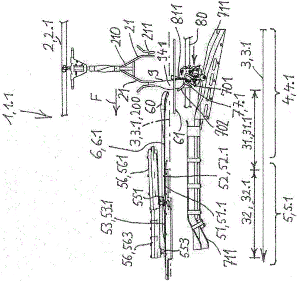
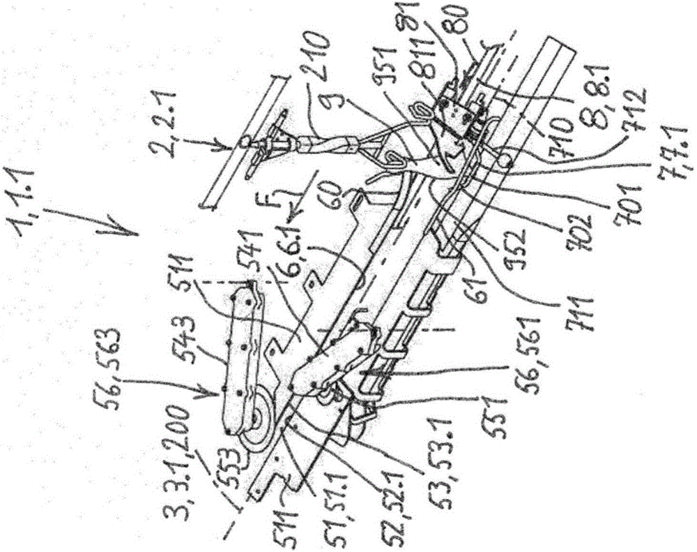
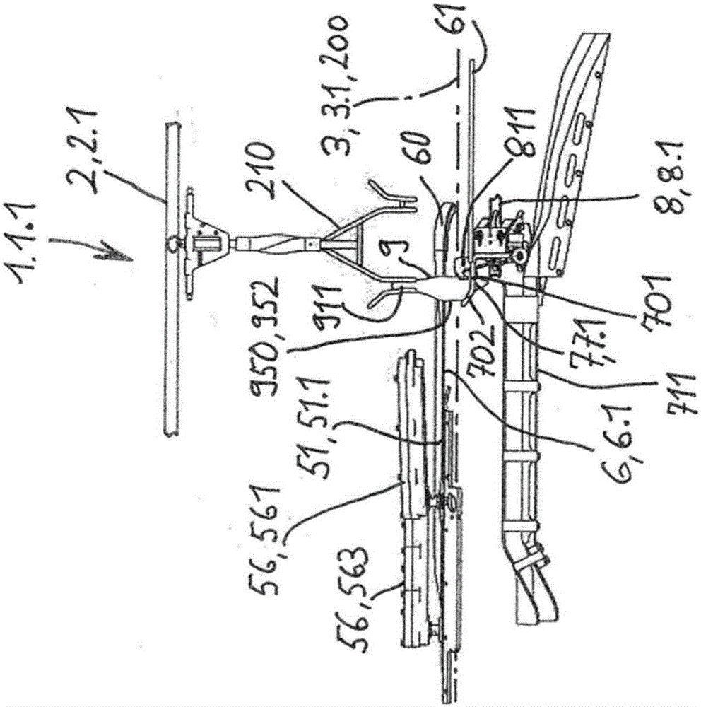
[0088] Figure 1A / B (Figure 1) to Figure 5A / B (FIG. 5) shows an embodiment of the first positioning device 1 of the invention, which is also called lateral positioning device 1.1. Figure 6A / B (Figure 6) to Figure 17A / B (FIG. 17) shows another embodiment of the positioning device 1 of the invention, a second positioning device called axial positioning device 1.2.

[0089] The invention will first describe the components and units of the two positioning devices 1 described above, which in general are also similarly applicable to the positioning devices according to example 1.1 and example 1.2 of the invention and to any positioning device. Frames, frames and connections, as well as drive motors or similar elements are not shown in the drawings in order to make the important parts of the device clearly visible in the drawings, wherein said parts and units are mounted on said frames, frames and are connected to each other by the connecting piece.

[0090] Each positionin...


PUM


Abstract

A positioning device (1) for positioning poultry legs (9) conveyed hung in single file comprises a flexing device (4) for flexing and positioning the poultry legs and a stationary holding and guiding device (5). The flexing device (4) forms a hooking device for suspending the poultry leg (9) at the region of the knee joint (93) in a holding and guiding slot (51) of the holding and guiding device (5). Travelling positioning elements (7) are formed by driven press elements which grip the poultry leg (9) from below on an axial leg side (940) to flex and lift said leg. Each travelling positioning element (7) forms, with a stationary positioning element (6), a functional pair of positioning elements (6, 7). One of the two positioning elements (6, 7) engages in the hollow of the knee (95) of the poultry leg (9) while the other positioning element (6.2; 7.1) is configured for placement on the thigh (92) on the front side (941) of the leg. Processing stations (56) can be arranged along the holding and guiding slot (51). In a method, carried out during the conveying, for removing the thigh meat from the poultry legs (9) conveyed in single file, said poultry legs are axially conveyed in a first said positioning device (1.1) with a transverse leading lateral side (950) of the leg and in a second said positioning device (1.2) with an axially leading knee cap side (940) of the leg. Cuts are made at the front side (941) of the leg and at the back side (942) of the leg along the first stationary holding and guiding slot (51.1). Cuts are made at the lateral sides (950) of the poultry leg along the second stationary holding and guiding slot (51.2), and the thigh meat (922) is pushed to the proximal end of the thigh bone (921).

Description

technical field [0001] The invention relates to a positioning device at a processing position for positioning poultry legs conveyed in rows along the conveying direction of a conveying line and provides a reference position for processing poultry legs, wherein the shanks and thighs of poultry legs are connected to each other by knee joints connected, and the axial side of the leg where the patella is located is the front side of the leg, and the other axial side of the leg where the hollow of the knee is located is the rear side of the leg, the positioning device includes: [0002] Conveyor device with conveying frames that move along the conveying line in the conveying direction and convey and hold poultry legs, along the entire conveying line of the positioning device, the poultry legs are clamped in the corresponding above-mentioned conveying frames by their ankle joint balls and The transport frame holds the poultry legs in a suspended position when the poultry legs are fe...

Claims


Application Information

Patent Timeline
IPC IPC(8): A22C21/00
CPCA22C17/0006A22C21/0023A22C21/0053A22C21/0076A22C21/0046A22C21/00
Inventor 赫尔曼纳斯·戈德弗里杜斯·威廉姆斯·埃伯斯威廉姆斯·亨里克斯·贝尔文蒂娜·吉策恩
Owner BAADER FOOD SYST DENMARK AS
Why Eureka
Eureka Blog
Learn More