traction suspension system

A suspension system and component technology, applied in the direction of suspension, elastic suspension, electric power device, etc., can solve problems such as increasing complexity

Active Publication Date: 2019-06-04
德萨动力有限公司
View PDF4 Cites 0 Cited by
  • Summary
  • Abstract
  • Description
  • Claims
  • Application Information

AI Technical Summary

Problems solved by technology

Some manufacturers have regained stability by adding linear drives parallel to or replacing the suspension, but by adding complexity (especi

Method used


Image

  • traction suspension system
  • traction suspension system
  • traction suspension system

Examples


Embodiment Construction

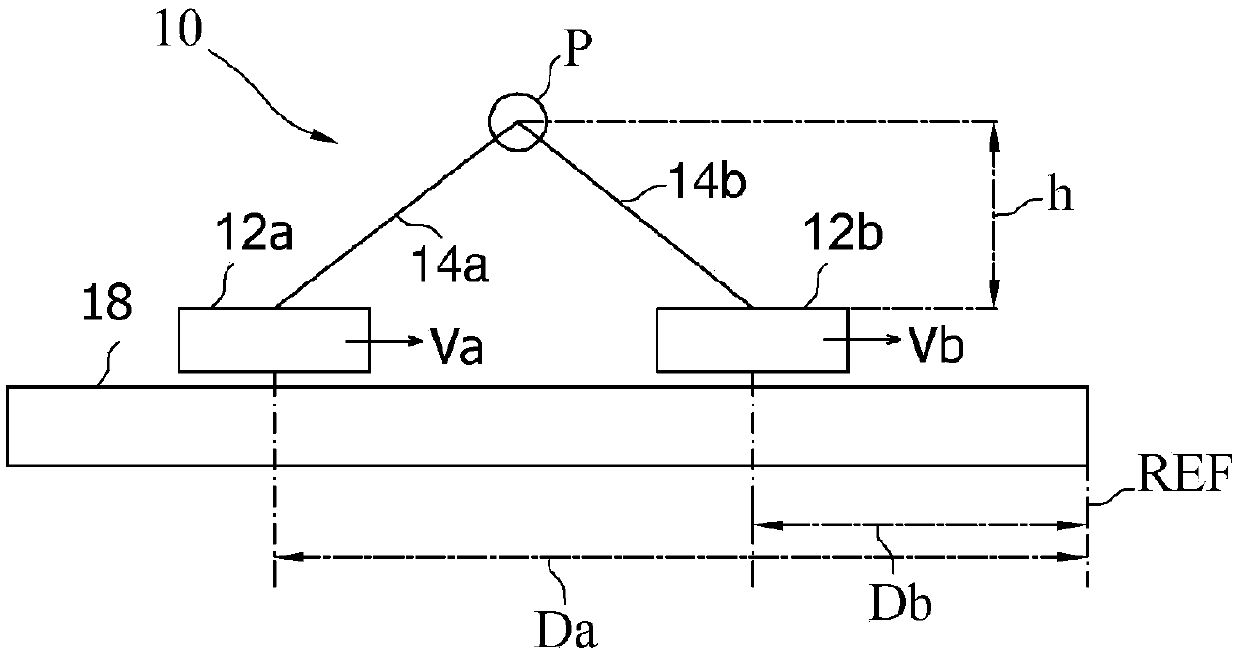
[0035] In order to understand the operation of the present invention, the basic principles are in figure 1 shown in . The system 10 comprises a track 12 on and relative to which the two units 12a, 12b can slide at relative velocities va, vb. The track has a zero reference REF, relative to which the cells 12a, 12b are at a distance Da, Db respectively. The speeds va, vb and / or the distances Da, Db are independently adjustable by control means (not shown).

[0036] Each unit 12a, 12b is connected to the same point P by a rigid arm 14a, 14b respectively. The point P is at a height h relative to the units 12a, 12b.

[0037] When the velocities va, vb are not equal, the speed difference will bring the units 12a, 12b closer or farther apart on the track 12, and thus the height h varies. Thus, by controlling the velocity va, vb and / or the distance Da, Db, the height h can be controlled.

[0038] Note that in system 10, the control of height h is independent of (i) the possible ...


PUM


Abstract

The invention discloses a suspension system (20) for a vehicle having a frame, the suspension system comprising: elements (R, 12) propelled by rolling on the ground; adapted to apply torque to the propulsion elements and can be mutually Two units (12a, 12b) that are independently controllable, wherein said two units are movable independently of each other relative to the propulsion element and are rigidly connected to the frame at the same point (P). By moving the or each unit relative to the propulsion element, the distance between the propulsion element and said point is changed.

Description

technical field [0001] The present invention generally relates to a traction suspension system, particularly in electric vehicles. Background technique [0002] When a car wheel travels over rough ground and encounters a hole or certain deformation of the road surface, it loses its attachment and lifts irregularly from the ground. The suspension has to counteract this, and the damper absorbs the bounce / oscillations of the suspension. [0003] The nature of electric vehicles allows for greater simplification, so great that in recent generations the traction system has been moved directly into the wheels, so that the weight of the wheels has increased (to about 30Kg), while the overall weight of the car has even decreased. [0004] Since the spring force of the suspension is approximately the weight of the vehicle divided by the number of wheels, the dynamic behavior of the wheels is less controlled because the suspension has to act on a larger mass. Some manufacturers have ...

Claims


Application Information

Patent Timeline
IPC IPC(8): B60G3/20B60G17/0165B60K7/00
CPCB60G3/207B60G17/0165B60G2200/144B60K7/0007B60G3/20B60G2204/30B60G2300/50B60G2401/17B60K2001/006B60K2007/0038B60K2007/0092B60K2007/003B60K2007/0053B60K2007/0069H02K1/182H02K16/00
Inventor A·吉罗托
Owner 德萨动力有限公司
Why Eureka
Try Eureka