Method and equipment for defining supporting structure for three-dimensional object to be made through stereolithography

A stereolithography, three-dimensional object technology, applied in the direction of 3D object support structure, processing and manufacturing, manufacturing tools, etc., can solve the problem of over-thick grid, large total volume of support structure, and insufficient total volume of support structure to properly provide three-dimensional support Objects and other issues, to achieve the effect of reducing costs and reducing the amount of materials

Inactive Publication Date: 2016-11-23
DWS SRL
View PDF3 Cites 8 Cited by
  • Summary
  • Abstract
  • Description
  • Claims
  • Application Information

AI Technical Summary

Problems solved by technology

[0018] The known method has the disadvantage that it does not allow the support structure to be defined in an optimal manner
[0020] An undersized support structure has the disadvantage that the total volume of the undersized support structure is insufficient to properly provide the function of supporting a three-dimensional object
[0021] Conversely, an oversized support structure has an oversized overall volume
[0022] Since the time required for the stereolithography process increases proportionally to the volume to be cured, an oversized support

Method used


Image

  • Method and equipment for defining supporting structure for three-dimensional object to be made through stereolithography
  • Method and equipment for defining supporting structure for three-dimensional object to be made through stereolithography
  • Method and equipment for defining supporting structure for three-dimensional object to be made through stereolithography

Examples


Embodiment Construction

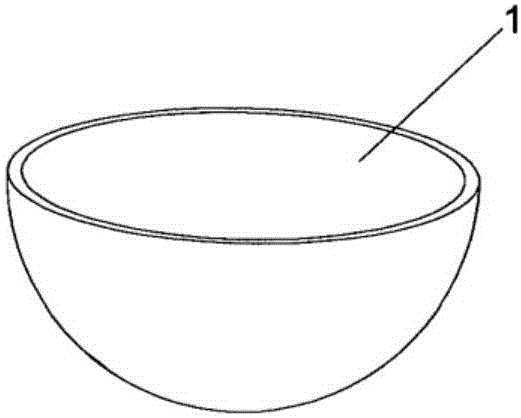
[0045] refer to figure 1 shown in and in figure 1 A three-dimensional object denoted by 1 in , describes the method of the invention for defining a support structure for a three-dimensional object to be produced by stereolithography.

[0046] It should thus be noted that the three-dimensional object 1 has deliberately been shown with a very simplified geometry compared to objects usually produced by stereolithography, in order to make the drawing clearer.

[0047] However, it is evident that the description provided above can be similarly applied to three-dimensional objects of any geometry.

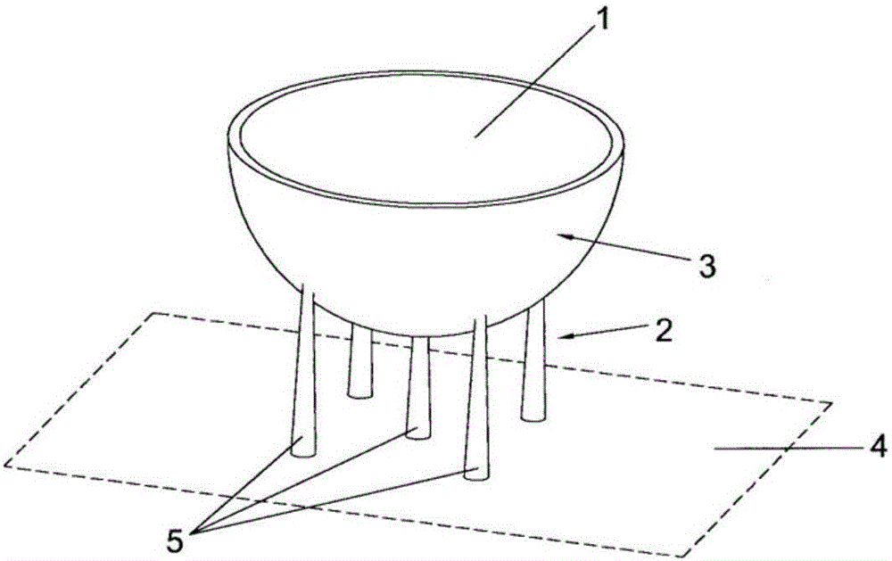
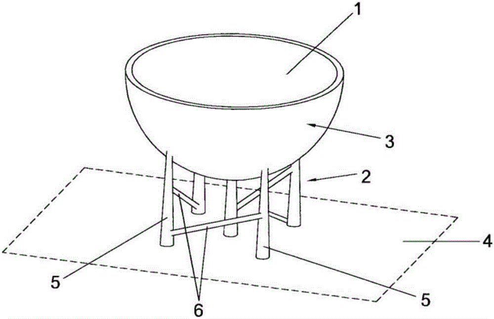
[0048] Firstly, the method comprises the step of defining a first surface 3 belonging to a three-dimensional object 1 to be supported.

[0049] Obviously, if necessary, a plurality of said first surfaces to be supported can be defined depending on the geometry of the object, the materials used in the stereolithography process and other parameters.

[0050] Obviously, the method of the...


PUM


Abstract

The invention is a computer-implemented method for defining a supporting structure (2) for a three-dimensional object (1) to be produced through a stereolithography process. The method comprises the following operations: defining a first surface (3) to be supported of the three-dimensional object (1) and a second surface (4) facing the first surface (3); defining elongated supporting elements (5) between the surfaces (3, 4); defining pairs of supporting elements (5); for each pair of supporting elements (5), defining an elongated reinforcing element (6) connecting the two supporting elements (5) of the pair. The definition of the pairs of supporting elements (5) comprises the following operations: defining a reference point (7) of each supporting element (5); defining a connected acyclic graph (8) having as vertices the reference points (7); for each edge (9) of the graph, defining one pair of supporting elements comprising the two supporting elements (5) corresponding to the ends of the edge (9). The definition of the pairs of supporting elements (5) comprises the further operation of defining an additional pair of supporting elements for each vertex having order 1 of the connected acyclic graph (8), the additional pair comprising a first supporting element (5) corresponding to the vertex having order 1 and a second supporting element (5) not connected to the first supporting element (5) through any edge (9).

Description

technical field [0001] The invention relates to a method for defining a support structure for a three-dimensional object to be produced by stereolithography and an apparatus for defining the support structure. Background technique [0002] As is well known, the process of stereolithography consists in producing three-dimensional objects by successively superimposing layers of the object itself. [0003] Each layer of the object is obtained by the curing of a material in liquid or pasty state, which takes place by selective exposure to light radiation. [0004] Typically, this material is a plastic-based compound that polymerizes when irradiated by said optical radiation. [0005] Each subsequent layer of the object is cured while in contact with the previous cured layer, which serves as a support for the subsequent layer. [0006] The process is controlled by a computer which is supplied with a first set of data representing the three-dimensional geometry of the object to ...

Claims


Application Information

Patent Timeline
IPC IPC(8): G06F17/50B29C67/00
CPCB33Y10/00G06F30/17B29C64/40B29C64/386B29C64/124B29C67/00B29C64/393B33Y50/02G06F2119/18B33Y30/00B29C64/10G06F30/00G06F2113/10B33Y50/00
Inventor 亚历山德罗·马罗津
Owner DWS SRL
Why Eureka
Try Eureka