Cargo conveying on-frame machine

A technology of goods and conveying devices, which is applied in the field of goods conveying racks, can solve the problems of high labor intensity, high belt cost, and high labor cost, and achieve improved stability and accuracy, reduced labor intensity, and a simple and compact structure Effect

Inactive Publication Date: 2016-11-30
HUNAN AGRICULTURAL UNIV
View PDF6 Cites 6 Cited by
  • Summary
  • Abstract
  • Description
  • Claims
  • Application Information

AI Technical Summary

Problems solved by technology

At present, in the process of loading, unloading, transferring, and putting goods on shelves in domestic supermarkets and express companies, it is mostly done manually with small carts, which requires many people, and there are problems with high manual labor intensity and low work efficiency. Low, high labor costs and other disadvantages
However, most of the domestic existing conveying equipment with telescopic function is limited to the use of belt conveyors. During the belt conveyor process, there are serious belt deviation phenomena. Not only is it difficult to adjust the deviation, but the belt damage caused by deviation will affect the belt. The service life, the cost of replacing the belt is very high, and at the same time, after the belt conveying unit is extended, it is difficult to realize the conveying of goods in two directions
There are also small and medium-sized express companies in foreign countries that use robots to deliver goods, but robots are expensive, costly to use and maintain, technically difficult to maintain, and have high professional requirements for users. This series of requirements largely limits The application and promotion of robot loading in small and medium-sized express companies

Method used


Image

  • Cargo conveying on-frame machine
  • Cargo conveying on-frame machine
  • Cargo conveying on-frame machine

Examples


Embodiment Construction

[0026] The present invention will be described in further detail below in conjunction with the accompanying drawings and specific embodiments.

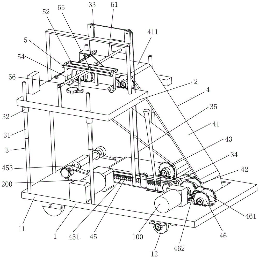
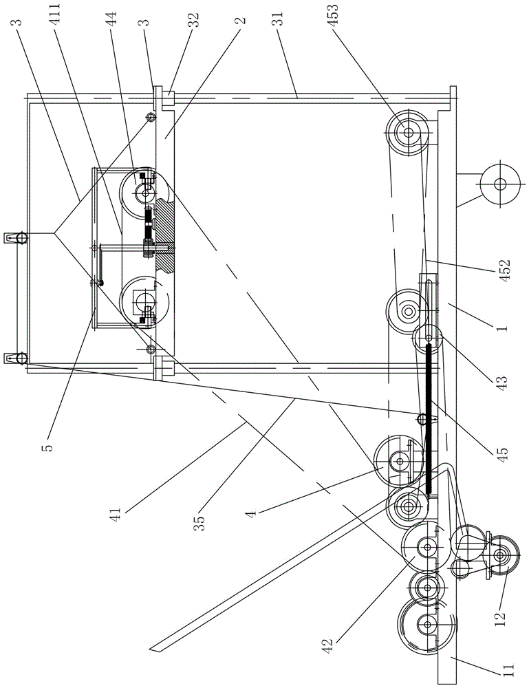
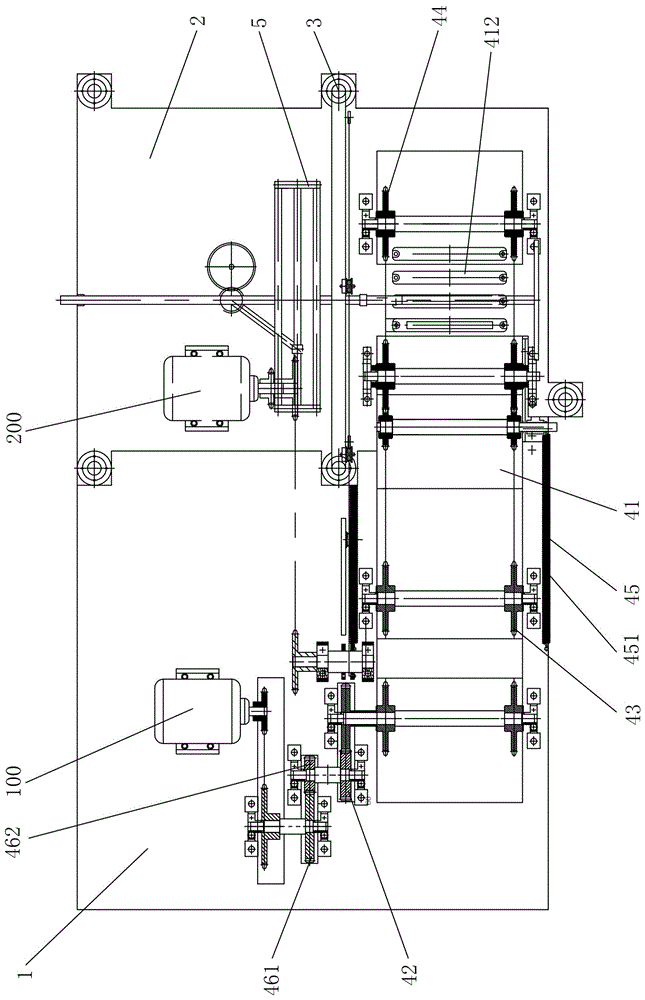
[0027] Such as Figure 1 to Figure 3 As shown, the cargo conveying rack machine of this embodiment includes a movable base 1 and a lifting platform 2, the lifting platform 2 is installed on the movable base 1 through a lifting device 3, and the lifting device 3 can drive the lifting platform 2 to move up and down to lift the platform The height of 2, between the movable base 1 and the lifting platform 2 is provided with a cargo conveying device 4 for conveying goods to the lifting platform 2, and the cargo conveying device 4 includes an endless conveyor belt 41 and a drive unit for driving the endless conveyor belt 41 to run The endless conveyor belt 41 includes a discharge section 411 that is located on the lifting platform 2 and rises and falls synchronously with the lifting platform 2. The lifting platform 2 is provided with a rack...


PUM


Abstract

The invention discloses a cargo conveying on-frame machine, which comprises a movable base and a lifting platform. The lifting platform is mounted on the movable base through a lifting device, and a cargo conveying device is arranged between the movable base and the lifting platform for conveying the cargos to the lifting platform The cargo conveying device comprises a loop conveyer belt and a driving unit for driving the loop conveyer belt. The loop conveyer belt includes a discharge section which is arranged on the lifting platform and moves up and down synchronously with the lifting platform. The lifting platform is provided with an on-frame pushing device for pushing the cargos on the discharge section. The cargo conveying on-frame machine has the advantages that efficiency is high, labor intensity and cost can be greatly reduced and so on.

Description

technical field [0001] The invention relates to the technical field of material conveying machinery, in particular to a cargo conveying rack machine. Background technique [0002] With the improvement of people's living standards, people consume more and more times, coupled with the rapid development of e-commerce, the frequency of goods circulation in the market is getting higher and higher. At present, in the process of loading, unloading, transferring, and putting goods on shelves in domestic supermarkets and express companies, it is mostly done manually with small carts, which requires many people, and there are problems with high manual labor intensity and low work efficiency. Low, high labor costs and other shortcomings. However, most of the domestic existing conveying equipment with telescopic function is limited to the use of belt conveyors. During the belt conveyor process, there are serious belt deviation phenomena. Not only is it difficult to adjust the deviation...

Claims


Application Information

Patent Timeline
Patent Type & Authority Applications(China)
IPC IPC(8): B65G41/00B65G23/44B65G23/38
CPCB65G23/38B65G23/44B65G41/008
Inventor 谢伟吴明亮罗海峰易鹏张贝贝
Owner HUNAN AGRICULTURAL UNIV
Why Eureka
Try Eureka