
Pad shoe dust removal device

A dust removal device and dust technology are applied in household cleaning devices, cleaning of boots and shoes, household appliances, etc., which can solve the problems of reducing suction force, damage or bending of the upper plate, weak product durability, etc., to ensure safety, ensure recognizable effects

Active Publication Date: 2018-09-21
ユーケアカンパニーリミテッド
View PDF5 Cites 0 Cited by
  • Summary
  • Abstract
  • Description
  • Claims
  • Application Information

AI Technical Summary

Problems solved by technology

[0009] However, in order to obtain the elastic force, the above-mentioned opening and closing unit needs to be combined with elastic members such as springs, and needs to be assembled in each inflow hole. Compared with the structure, the demand for assembling accessories is greater, so there are complicated assembly and many assembly process steps. , rising overall production costs, etc.
[0010] In addition, in the conventional structure, the above-mentioned elastic member is arranged in the collection channel, and the foreign matter sucked through the inflow hole will be stuck on the elastic member, and the opening and closing operation cannot be performed smoothly, which not only reduces the suction force, but also requires frequent repairs for maintenance. It is cumbersome; regardless of whether there is a supporting member supporting the upper plate, it is very fragile, and the upper plate may be damaged or bent due to the weight of the user, and there is a problem that the durability of the product is weak

Method used


Image

  • Pad shoe dust removal device
  • Pad shoe dust removal device
  • Pad shoe dust removal device

Examples


Embodiment Construction

[0028] The present invention will be described in detail below with specific embodiments with reference to the drawings.

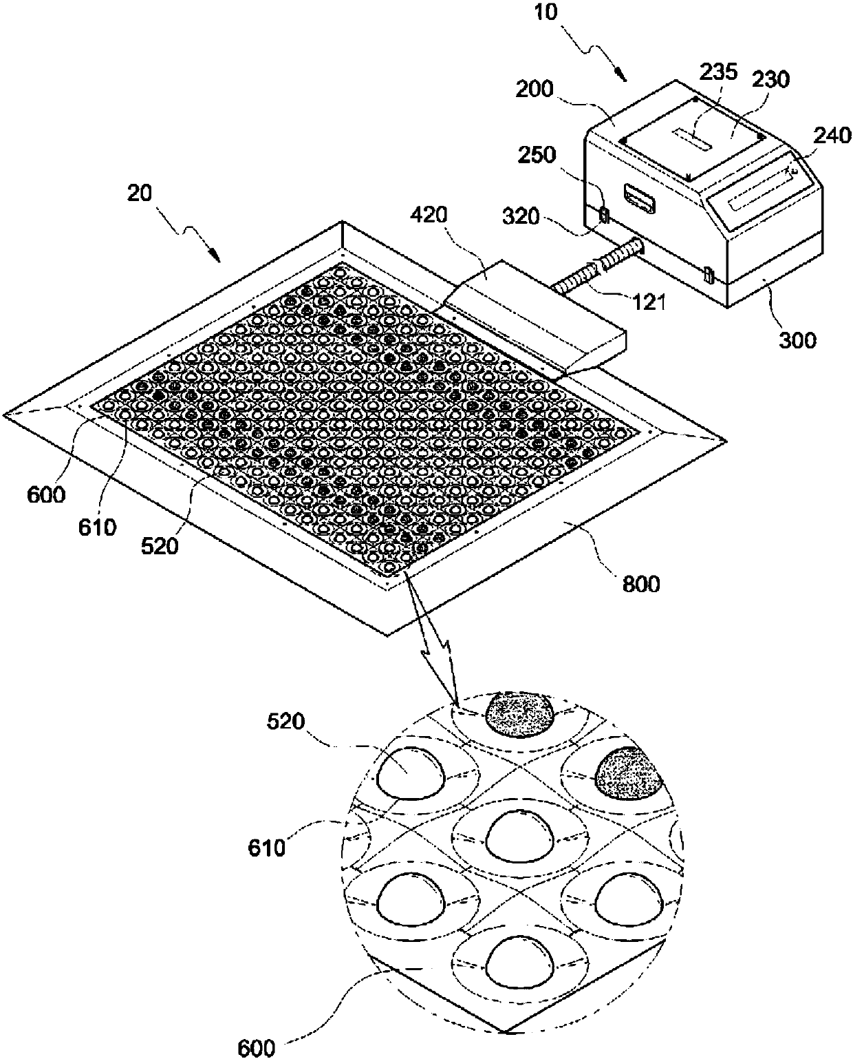
[0029] Such as figure 1 As shown, the cushion shoe dust removal device of the present invention is installed on the floor of the entrance and exit of the facility, and includes a vacuum suction device 10 and a pad body 20. The vacuum suction device 10 is installed on one side. The pad body 20 is absorbed by the vacuum suction device 10 Inhale the dust on the shoes of the passengers.

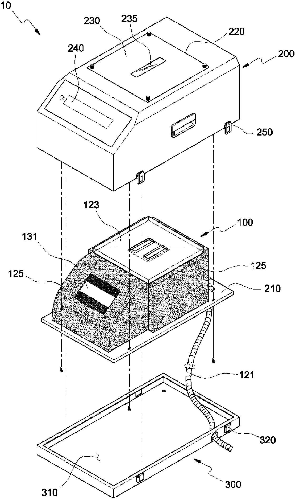
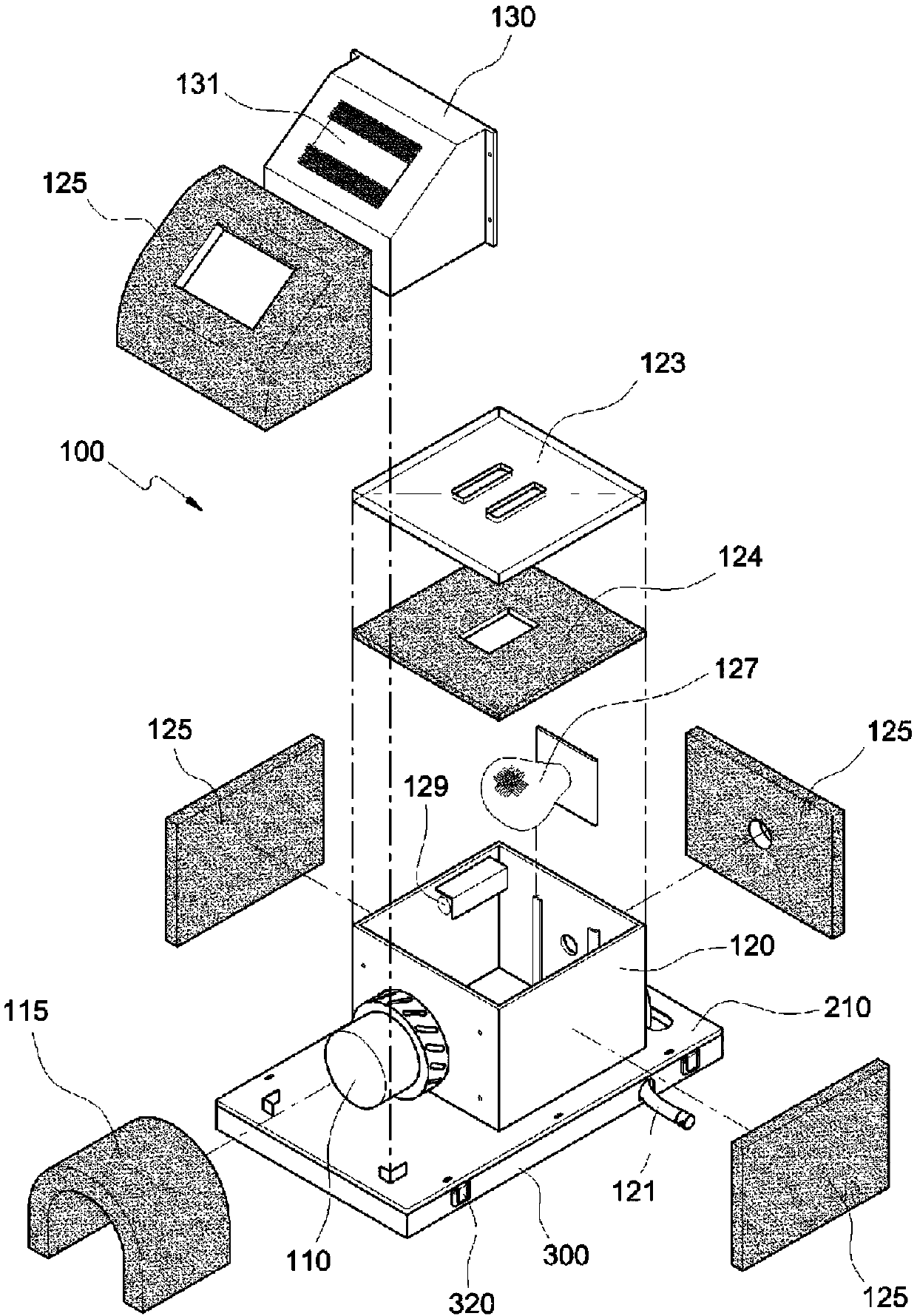
[0030] Here like Figure 2 to Figure 4 As shown, the vacuum suction device 10 includes: a suction unit 100, which uses the suction force of the suction motor 110 provided on one side of the trap box 120 to use the suction pipe connected to the connection pipe 410 of the pad body 20 121, the dust of the mat body 20 is sucked and collected in the collecting box 120, and in order to eliminate the noise of the suction motor 110 and the collecting box 120, a second section is provided ...


PUM


Abstract

The present invention relates to a mat-type shoe dust remover which is installed on the floor of an entrance of a facility so as to create a pleasant indoor environment by removing foreign materials such as dust on the bottom of shoes of an entering person. The mat-type shoe dust remover is installed on the floor of an entrance of a facility and has a mat body for sucking in the dust on the shoes of an entering person by means of suction force of a vacuum suction device provided at one side. The vacuum suction device comprises: a suction means which sucks in and collects the dust on the mat body through a suction pipe, which is connected to a connection pipe in the mat body, by means of the suction force of a suction motor provided at one side of a collection box, and which is provided with first and second absorption materials along the periphery so as to reduce noise of the suction motor and the collection box; an outer case connected to a bottom plate formed at the lower side of the suction means and surrounding the outer periphery of the suction means; and a base fixedly installed on the floor of one side of the entrance and detachably connected to the lower end of the outer case, and having a suction pipe accommodating unit for accommodating the suction pipe therein. The present invention creates a pleasant environment by reducing, through sound absorption materials, vibration and noise generated during the suction of dust, enables a user to check with the naked eyes the collected dust through an outer cover having a sight glass and to easily discharge the dust, and secures visibility through a guide lamp, thereby providing security so that an entering person can easily pass during the night or blackout.

Description

Technical field [0001] The present invention relates to a cushion-type shoe dust removal device that is installed on the floor of an entrance and exit to remove dust and other foreign objects on the soles of the inbound and outbound shoes to create a refreshing indoor environment. In more detail, the present invention relates to a cushion-type shoe dust removal device. Regardless of the area of ​​the pad body, the opening and closing member of the inflow hole only opens and closes the inflow hole on the part that a person steps on, which not only concentrates the suction force, but also reduces the components of the opening and closing unit to a minimum, reducing manufacturing costs. And by attaching the sound-absorbing material to the vacuum suction device, the vibration and noise generated during the inhalation of dust can be eliminated, and a comfortable environment can be created. The dust trapped in the vacuum suction device can be visually confirmed, and the dust can be eas...

Claims


Application Information

Patent Timeline
Patent Type & Authority Patents(China)
IPC IPC(8): A47L23/22
CPCA47L23/22
Inventor 申载云
Owner ユーケアカンパニーリミテッド
Learn More