
Stirring cup driven by heat energy

A stirring cup and thermal energy technology, applied in the field of cups, can solve problems affecting the practicality and aesthetics of the cup, affecting the installation space of the stirring device, and increasing the thickness of the bottom of the cup, so as to achieve convenient and thorough cleaning, increase power generation, and increase heat. The effect of the exchange area

Inactive Publication Date: 2016-12-07
祁高鹏
View PDF1 Cites 9 Cited by
  • Summary
  • Abstract
  • Description
  • Claims
  • Application Information

AI Technical Summary

Problems solved by technology

At the same time, the thermoelectric power generation sheet and its heat dissipation device added at the bottom of the cup will also affect the installation space of the stirring device at the bottom of the stirring cup, or increase the thickness of the bottom of the cup, which will affect the practicability and aesthetics of the cup

Method used


Image

  • Stirring cup driven by heat energy
  • Stirring cup driven by heat energy
  • Stirring cup driven by heat energy

Examples


Embodiment Construction

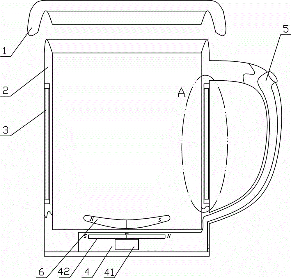
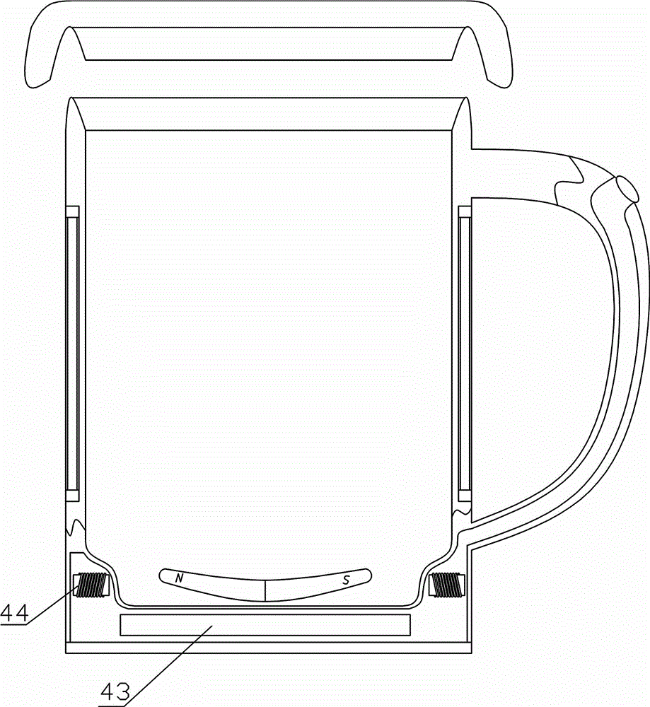
[0026] like figure 1 , 3 Among them, a stirring cup driven by heat energy includes a cup body 2, preferably also provided with a cup cover 1, and a thermal insulation layer is provided inside the cup cover 1. A power generating device is arranged in the cup body 2, and the generating device is connected with the stirring device;

[0027] The power generation device includes a thermoelectric power generation sheet 33 .

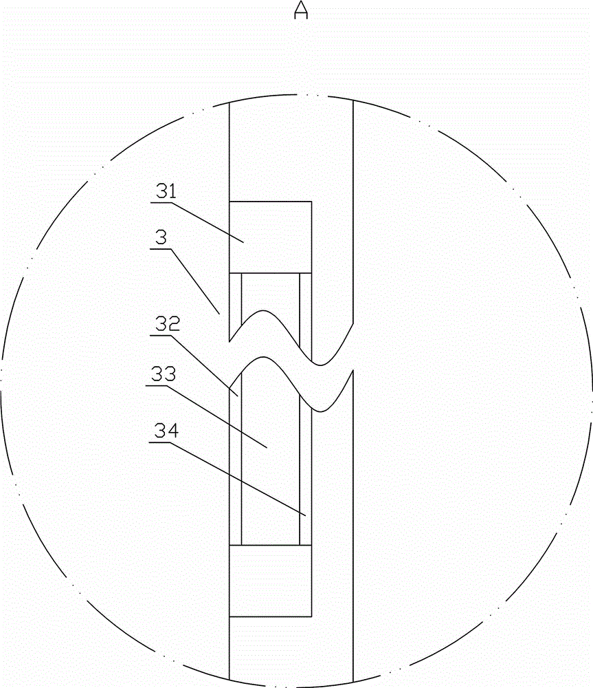
[0028] The preferred solution is as figure 2 Among them, in the power generation device described above, the thermoelectric power generation sheet 33 is located in the side wall of the cup body 2, and the inner and outer layers of the thermoelectric power generation sheet 33 are respectively provided with an inner layer heat conduction sheet 34 and an outer layer heat conduction sheet 32, and the thermoelectric generation sheet 33 The upper end and the lower end are provided with a heat insulating layer 31 . The material of the inner layer heat conduction ...


PUM


Abstract

Provided is a stirring cup driven by heat energy. The stirring cup comprises a cup body which is internally provided with a power generation device, the power generation device is connected with a stirring device, and the power generation device comprises a temperature difference power generation piece. In the power generation device, the temperature difference power generation piece is located in the side wall of the cup body, an inner layer heat conducting plate and an outer layer heat conducting plate are arranged on the inner side and the outer side of the temperature difference power generation piece respectively, and heat insulating layers are arranged at the upper end and the lower end of the temperature difference power generation piece respectively. In the stirring device, a driving device drives a permanent magnet blade to rotate through magnetic force. According to the stirring cup driven by the heat energy, the energy-saving effect is achieved by utilizing the temperature difference power generation piece to generate electricity to drive the stirring device to rotate. In the optimal scheme, the temperature difference power generation piece is arranged on the side wall of the cup body, the heat exchange area is increased, and the generating capacity is increased. The mode that the permanent magnet blade is driven by the magnetic force to rotate is adopted, no fixed connection exists between the permanent magnet blade and the cup body, the inner wall of the cup body is complete, no transmission shaft exists, and no transmission shaft hole exists.

Description

technical field [0001] The invention relates to a cup, in particular to a stirring cup driven by heat energy. Background technique [0002] In the existing electric stirring cup, the battery drives the motor, and the motor drives the stirring blades to stir the contents in the cup. The prior art is powered by a storage battery, which requires frequent charging, wastes energy, is not environmentally friendly, and is not economical. The existing thermoelectric power generation water cup generates electricity by installing a thermoelectric power generation piece at the bottom of the cup. On the one hand, the contact area between the thermoelectric power generation piece and the hot water is small, and the efficiency is low; The heat dissipation of the cold surface of the thermoelectric power generation sheet is limited to a large extent, and a complex heat dissipation device needs to be added. Therefore, this installation method has low efficiency and high cost. For example, ...

Claims


Application Information

Patent Timeline
Patent Type & Authority Applications(China)
IPC IPC(8): A47G19/22A47J43/04A47J43/08
Inventor 祁高鹏
Owner 祁高鹏
Learn More