Dynamic Headspace Degasser

A technology of dynamic headspace degassing and degassing tank, which is applied in the direction of measuring devices, liquid degassing, material inspection products, etc., which can solve the problem that the long equilibration time can not quickly respond to the change of insulating oil components, affect the insulation performance of insulating oil, and ensure reliability. Poor performance and unsuitable problems, to achieve the effect of low cost, good air tightness and high consistency

Active Publication Date: 2018-08-07
南瑞通用电气智能监测诊断(武汉)有限公司
View PDF4 Cites 0 Cited by
  • Summary
  • Abstract
  • Description
  • Claims
  • Application Information

AI Technical Summary

Problems solved by technology

The thin film permeation method has the advantages of simple structure and reliable operation, but its long equilibration time cannot quickly respond to the change of components in insulating oil
Due to the high gas content in the oil after degassing, the existing instruments using the dynamic headspace degassing method tend to form many small bubbles when feeding back to the transformer, which affects the insulation performance of the insulating oil, so they cannot be directly fed back to the transformer
The treatment measure of the existing instrument is to directly discharge the degassed oil sample to cause the consumption of insulating oil
The vacuum degassing method has the highest degassing efficiency, but in order to ensure the degassing effect, the vacuum degree of the system needs to be strictly controlled, so the requirements for the vacuum degree of the system and the vacuum pump are very high, resulting in its complex structure and poor reliability, which is not suitable for online detection applications

Method used


Image

  • Dynamic Headspace Degasser
  • Dynamic Headspace Degasser
  • Dynamic Headspace Degasser

Examples


Embodiment Construction

[0025] In order to have a clearer understanding of the technical features, purposes and effects of the present invention, the specific implementation manners of the present invention will now be described in detail with reference to the accompanying drawings.

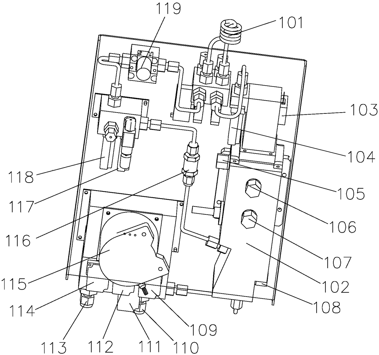
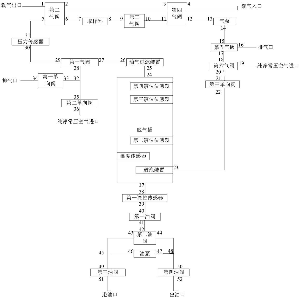
[0026] like figure 1 , figure 2 As shown, the dynamic headspace degassing device of the present invention includes a degassing tank 102, a gas circuit part and an oil circuit part. The gas circuit part and the oil circuit part are respectively connected with the degassing tank 102, and the bottom of the degassing tank 102 is provided with a bubbling device. A temperature sensor is provided at the bottom of the degassing tank 102 .

[0027] The gas path part includes a circulation pipeline, and the circulation pipeline is provided with a first air valve 104, a second air valve 118, a sampling loop 101, a third air valve 117, a fourth air valve, an air pump 119, a fifth air valve and a fourth air valve. Six air valves...


PUM


Abstract

The invention relates to a dynamic headspace degassing device which comprises a degassing tank (102), a gas channel part and an oil channel part. The gas channel part and the oil channel part are connected with the degassing tank (102). The bottom of the degassing tank (102) is provided with a bubbling device. The gas channel part comprises a circulation pipeline. The circulation pipeline is sequentially provided with a first gas valve (104), a second gas valve (118), a sampling ring (101), a third gas valve (117), a fourth gas valve, a gas pump (119), a firth gas valve and a sixth gas valve. The oil channel part comprises an oil pump (115), a first oil valve (112), a second oil valve (114), a third oil valve (109) and a fourth oil valve (111). According to the device, a small number of oil samples are consumed in single measurement, the influences of transformer crude oil sample concentration can be reduced to the maximum on the condition of continuous high-density measurement, modular structural part design is adopted, the cost is low, no complex mechanical device is arranged, and the reliability of the whole device is greatly improved.

Description

technical field [0001] The invention relates to the field of on-line monitoring of transformer oil, in particular to a dynamic headspace degassing device. Background technique [0002] One of the most critical links to realize the online monitoring of dissolved gas in insulating oil is to realize oil-gas separation. The stability and accuracy of oil-gas separation technology will directly determine the stability and test accuracy of online monitoring equipment. Three popular oil and gas separation methods are membrane permeation method, headspace degassing method and vacuum degassing method. The film permeation method has the advantages of simple structure and reliable operation, but its long equilibration time cannot quickly respond to the change of components in the insulating oil. Due to the high gas content in the oil after degassing, the existing instruments using the dynamic headspace degassing method tend to form many small bubbles when feeding back to the transforme...

Claims


Application Information

Patent Timeline
Patent Type & Authority Patents(China)
IPC IPC(8): B01D19/00G01N33/28
CPCB01D19/00G01N33/2841
Inventor 罗维方卫星毛知新干东方肖禾卉
Owner 南瑞通用电气智能监测诊断(武汉)有限公司
Why Eureka
Try Eureka