A transducer unit of an ultrasonic transducer

A technology of ultrasonic transducers and transducer units, which is applied in the direction of fluids that utilize vibrations, can solve problems such as reducing transduction efficiency, and achieve the effects of improving transduction efficiency, good fit, and stable working performance

Active Publication Date: 2019-03-15
哈尔滨龙声超声技术有限公司
View PDF7 Cites 0 Cited by
  • Summary
  • Abstract
  • Description
  • Claims
  • Application Information

AI Technical Summary

Problems solved by technology

[0003] In practical applications, although non-solid filling layers such as oil layers play a certain role in heat dissipation, ultrasonic waves will generate a lot of loss after passing through non-solid filling layers such as oil layers, reducing the conversion efficiency.

Method used


Image

  • A transducer unit of an ultrasonic transducer
  • A transducer unit of an ultrasonic transducer
  • A transducer unit of an ultrasonic transducer

Examples


Embodiment 1

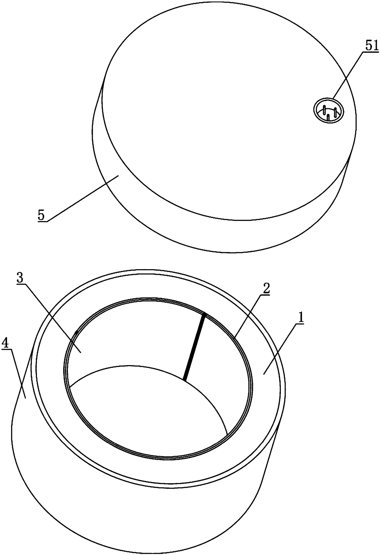
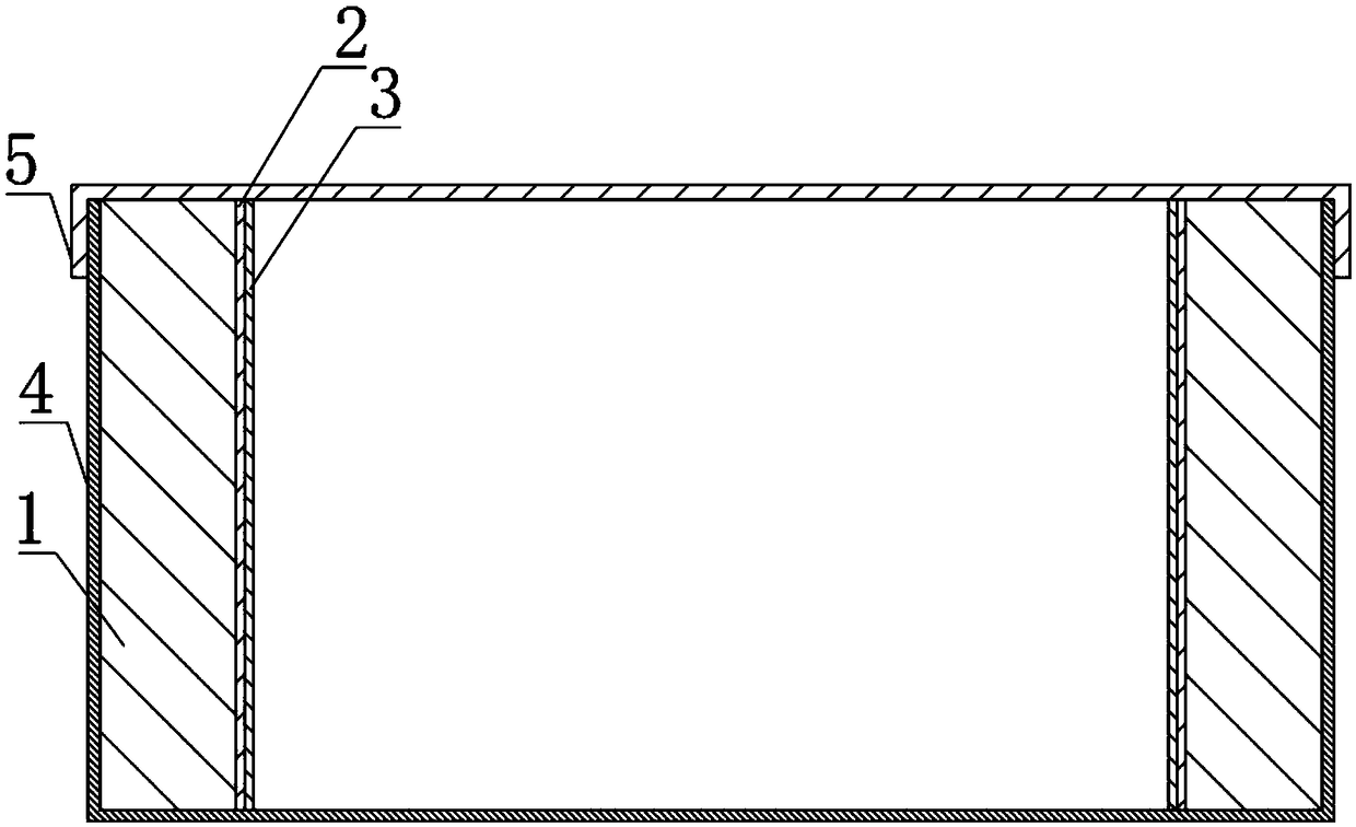
[0030] Such as figure 1 and figure 2 As shown, the transducer unit of the ultrasonic transducer provided by the embodiment of the present invention includes a sealed indium steel shell and a piezoelectric ceramic ring 1 arranged in the indium steel shell, wherein the piezoelectric ceramic ring 1 includes a piezoelectric ceramic ring 1 An electric ceramic ring body, and an inner silver layer inside the piezoelectric ceramic ring body and an outer silver layer outside the piezoelectric ceramic ring body, and the outer silver layer is arranged close to the indium steel shell.

[0031] Compared with the traditional transducing unit, the oil medium is removed between the piezoelectric ceramic ring 1 and the shell in this embodiment, which improves the transducing efficiency. Meanwhile, the outer silver layer of the piezoelectric ceramic ring 1 is close to the indium steel shell, The heat generated by the piezoelectric ceramic ring 1 is dissipated through the indium steel shell, a...

Embodiment 2

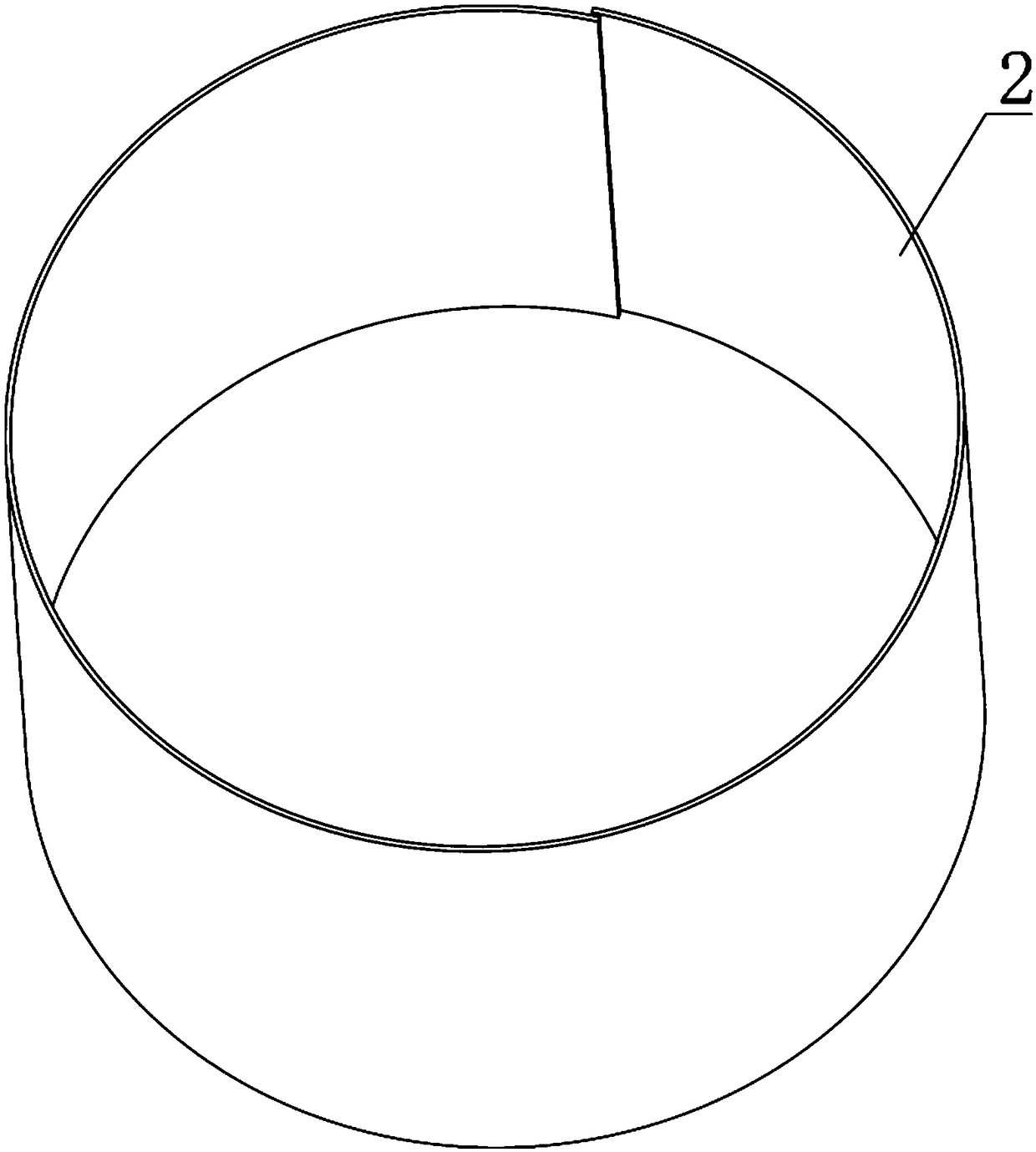
[0043] Such as Figure 4 and Figure 5 As shown, the second embodiment is basically the same as the first embodiment, and the similarities will not be repeated. The difference is that the casing 3 is a cylindrical structure with openings at both ends. When assembling, the cylindrical The casing 4 is sleeved on the outside of the piezoelectric ceramic ring 1 , and then two covers 5 are respectively covered on the two ends of the casing 4 .

[0044] Preferably, an aviation plug is arranged on one of the covers 5 .

[0045] In summary, the transducing unit of the ultrasonic transducer provided by the present invention removes the oil medium between the piezoelectric ceramic ring and the housing, thereby improving the transducing efficiency, and at the same time, the outer silver layer of the piezoelectric ceramic ring is closely attached to the The indium steel shell allows the heat generated by the piezoelectric ceramic ring to dissipate through the indium steel shell. Without...


PUM


Abstract

The invention relates to the technical field of ultrasonic transduction, in particular to a transduction unit for an ultrasonic transducer. The transduction unit comprises a sealed invar shell and a piezoelectric ceramic ring arranged in the invar shell. A silver layer on the outer side of the piezoelectric ceramic ring is tightly attached to the invar shell, an oil medium is removed from the position between the piezoelectric ceramic ring and the shell, and the transduction efficiency is improved. Meanwhile, the silver layer on the outer side of the piezoelectric ceramic ring is tightly attached to the invar shell, so that heat generated by the piezoelectric ceramic ring is dissipated out through the invar shell. Under the condition that heat dissipation is not affected, the problem that ultrasonic wave losses of a transduction unit of an existing ultrasonic transducer exist is solved, in addition, a sealed shell structure is adopted in the transduction unit, so that transmission media are prevented from entering the transducer in the use process, in addition, the heat expansion coefficient of invar is smaller than the heat exchange coefficient of piezoelectric ceramic, so that the fitness between the piezoelectric ceramic ring and the invar shell is better along with increasing of the temperature, and the working performance of the transduction unit is more stable.

Description

technical field [0001] The invention relates to the technical field of ultrasonic transducers, in particular to a transducer unit of an ultrasonic transducer. Background technique [0002] Existing ultrasonic transducers generally include a shell, one or more piezoelectric ceramic elements, and a non-fixed filling layer arranged between the shell and the piezoelectric ceramic elements, wherein the non-fixed filling layer is the heat dissipation of the transducer. The important components required, especially the large ultrasonic transducer, generate a lot of heat. In order to effectively dissipate heat, a non-fixed filling layer for heat dissipation must be provided between the piezoelectric ceramic element and the housing. The most commonly used The non-solid fill layer is oil. [0003] In practical applications, although non-solid filling layers such as oil layers play a certain role in heat dissipation, ultrasonic waves will generate a lot of loss after passing through n...

Claims


Application Information

Patent Timeline
Patent Type & Authority Patents(China)
IPC IPC(8): B06B1/06
CPCB06B1/06B06B2201/55
Inventor 曾嫣赵骁
Owner 哈尔滨龙声超声技术有限公司
Why Eureka
Try Eureka