Slotted pressure pliers for main drive lock nut

A main reducer and lock nut technology, which is applied to nuts, lock fasteners, screws, etc., can solve problems such as manual locking difficulties, achieve the effect of protecting workpieces and operating safety, and saving operating time

Active Publication Date: 2018-02-02
ANHUI ANKAI FUTIAN SHUGUANG AXLE CO LTD
View PDF5 Cites 0 Cited by
  • Summary
  • Abstract
  • Description
  • Claims
  • Application Information

AI Technical Summary

Problems solved by technology

[0003] The purpose of the present invention is to solve the difficult problem of manual locking of the lock nut of the traditional main reducer, and provide a slotted pressure pliers for the lock nut of the main reducer, which improves the consistency, safety and reliability after locking

Method used


Image

  • Slotted pressure pliers for main drive lock nut
  • Slotted pressure pliers for main drive lock nut
  • Slotted pressure pliers for main drive lock nut

Examples


Embodiment Construction

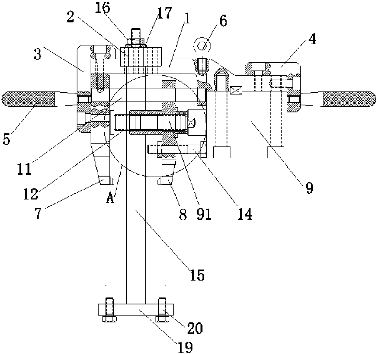
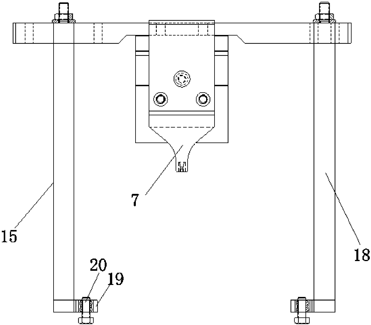
[0022] Refer to attached figure 1 and figure 2 A main reducer locknut slotted pressure pliers shown includes a clamp holder 1 and a positioning rod holder 2 arranged on the clamp holder 1; the two clamp holders 1 Two handles 5 are symmetrically arranged on the fixed plate 3 and the oil cylinder baffle 4, which is convenient for workers to move by hand; , easy to lift.

[0023] The fixed plate 3 and the oil cylinder baffle 4 are fixed on the clamping pliers fixing seat 1 through a taper pin, the fixed clamping pliers 7 are installed on the fixed plate 3, the oil cylinder 9 is installed on the oil cylinder baffle plate 4, and the fixed clamping pliers 7 and the oil cylinder 9 are opposite to each other. Set, the piston rod 91 end of the oil cylinder 9 is vertically directed to the fixed clamp 7, and the slide clamp 8 is fixed on the piston rod 91.

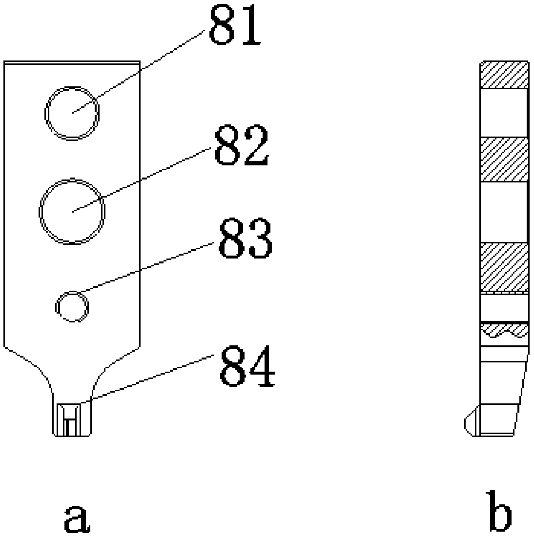
[0024] refer to Figure 4 and Figure 5 As shown, the guide rod installation hole 81, the piston rod installation hole 82 and...


PUM


Abstract

The invention relates to the technical field of assembly of automobile parts, in particular to a grooving pressure clamp for a locking nut of a main speed reducer. The grooving pressure clamp comprises a pressing clamp fixing base and a positioning rod fixing base arranged on the pressing clamp fixing base; the two ends of the pressing clamp fixing base are oppositely equipped with a fixed pressure clamp and an oil cylinder; a piston rod end of the oil cylinder perpendicularly points to the fixed pressure clamp; a slide pressing clamp is fixedly arranged on the piston rod; the slide pressing clamp and the fixed pressing clamp are oppositely arranged, and the bottom end of the slide pressing clamp and the bottom end of the fixed pressing clamp are positioned on the same horizontal line; the bottom end of the slide pressing clamp is equipped with a blunt knife edge type pressure head; and a bump type pressure head is arranged at the bottom end of the fixed pressing clamp. The grooving pressure clamp can replace a conventional manual locking mode, so that grooving and pressing consistency and reliability of the locking nut of the main speed reducer are guaranteed, anti-loosening effect is realized better, and the automatic production development direction is met better.

Description

technical field [0001] The invention relates to the technical field of assembly of automobile parts, in particular to a slotting pressure pliers for locking nuts of a final reducer. Background technique [0002] In the field of auto parts assembly, lock nuts are used in various parts. After the lock nuts are tightened, they need to be locked. Now most of them adopt the slotted locking method, which is tightened manually to prevent loosening. However This kind of assembly method is backward, has poor consistency, wastes manpower, and also has hidden dangers of loosening. Contents of the invention [0003] The purpose of the present invention is to solve the difficult problem of manual locking of the lock nut of the traditional main reducer, and provide a slotted pressure pliers for the lock nut of the main reducer, which improves the consistency, safety and reliability after locking. [0004] In order to solve the above problems, the present invention adopts the following ...

Claims


Application Information

Patent Timeline
Patent Type & Authority Patents(China)
IPC IPC(8): B23D31/00F16B39/02
CPCB23D31/002F16B39/02
Inventor 刘志周宗建李琼韩娜高欢
Owner ANHUI ANKAI FUTIAN SHUGUANG AXLE CO LTD
Why Eureka
Try Eureka