Resistor inversion conversion tooling and resistor inversion conversion method

A technology for resistors and inversion, which is applied in the field of inversion conversion tooling, which can solve the problems of fragile lead wires of resistors, difficulty in inversion, and low product yield, so as to reduce damage rate, improve quality and yield, and improve work efficiency Effect

Active Publication Date: 2018-09-18
NANJING SHIHENG ELECTRONICS
View PDF3 Cites 0 Cited by
  • Summary
  • Abstract
  • Description
  • Claims
  • Application Information

AI Technical Summary

Problems solved by technology

However, the lead wire of the resistor is fragile, so it brings difficulties to the mold, and a little carelessness will form a defective product, resulting in a low product yield

Method used


Image

  • Resistor inversion conversion tooling and resistor inversion conversion method
  • Resistor inversion conversion tooling and resistor inversion conversion method
  • Resistor inversion conversion tooling and resistor inversion conversion method

Examples


Embodiment Construction

[0022] The present invention will be described in further detail below in conjunction with the accompanying drawings.

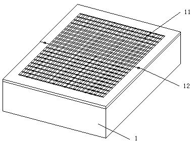
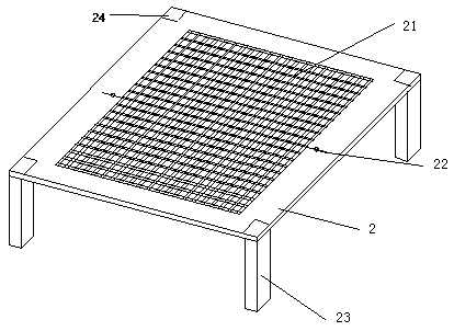
[0023] see Figure 1 to Figure 5 , showing various devices used in the resistor inversion conversion tooling of the present invention. figure 1 is bottom mold 1, figure 2 It is the middle model 2. The so-called inverted mold conversion is to flip the batch resistors originally in the first bottom mold to another second bottom mold without resistors, so as to realize the transfer and flip of the resistors. Both the upper surface of the bottom mold and the middle mold have a grid area and a non-grid area. The non-grid area surrounds the grid area. The grid area contains a plurality of grids, and gaps are formed between the grids. The gap between the grids 21 can pass through the resistor, and the gap between the grids of the bottom mold 11 is a structure in which the aperture decreases from top to bottom, so that the chip body of the resistor can be stuck ...


PUM


Abstract

The invention discloses a die overturning transformation tool for resistors. The tool comprises a bottom die, a middle die, a cover plate, a first tooth comb and a second tooth comb. A grid area and a non-grid area are arranged on the upper surface of each of the bottom die and the middle die, wherein a gap exists between every two adjacent grids, and the resistors can pass through the gaps between the grids of the middle die. The gaps between the grids of the bottom die are of a structure with the apertures gradually reduced from top to bottom. The bottom die can be completely covered with the middle die, and the gaps of the grids of the middle die correspond to the gaps of the grids of the bottom die. The cover plate is provided with a plate face and a handle, wherein the area of the plate face at least can cover the grid area of the bottom die and the grid area of the middle die. Each of the first tooth comb and the second tooth comb is provided with comb teeth and a tooth comb handle, wherein the front ends of the comb teeth are provided with tooth tops, and a tooth gap exists between every two adjacent comb teeth. According to the die overturning transformation tool for the resistors, batched die overturning transformation of the resistors is achieved, the working efficiency is improved, and the damage rate in the die overturning transformation process of the resistors is reduced.

Description

technical field [0001] The invention belongs to the field of electronic device manufacturing, and in particular relates to an inversion conversion tooling involved in the manufacturing process of a resistor and a method for inversion conversion of the resistor. Background technique [0002] Resistors are difficult to operate directly due to their small size. Generally, they are arranged and fixed by means of molds, paper tapes, adhesive tapes and other devices and operated in batches to have better operating efficiency. For batch resistors placed on molds, it is inevitable to involve switching from one mold to another during operation to facilitate the transfer and subsequent operation of resistors. For example Figure 8 Resistors of the kind included in the operation are placed in such figure 1 In the mold shown in , there is a grid on the mold, and holes are formed between the grids, and the holes are large and small at the top and small at the bottom, just enough to all...

Claims


Application Information

Patent Timeline
Patent Type & Authority Patents(China)
IPC IPC(8): B29C33/30
CPCB29C33/30
Inventor 汪洋
Owner NANJING SHIHENG ELECTRONICS
Why Eureka
Try Eureka