Eureka AIR delivers breakthrough ideas for toughest innovation challenges, trusted by R&D personnel around the world.

Optical fiber line structure unit and optical fiber line

A technology for optical fiber lines and structural units, applied in the field of optical fiber protection devices, can solve problems such as cumbersome adjustment process, and achieve the effects of high applicability, strong resilience, and stable relative position

Active Publication Date: 2020-12-01
CHANGCHUN INST OF OPTICS FINE MECHANICS & PHYSICS CHINESE ACAD OF SCI
View PDF12 Cites 0 Cited by
  • Summary
  • Abstract
  • Description
  • Claims
  • Application Information

AI Technical Summary

Problems solved by technology

If an additional attitude fixing device is designed, firstly, it needs to be fixed in more places according to the length of the optical fiber, and secondly, the adjustment process will be limited by the actual structure and become more cumbersome

Method used


Image

  • Optical fiber line structure unit and optical fiber line
  • Optical fiber line structure unit and optical fiber line

Examples


Embodiment Construction

[0026] In order to make the object, technical solution and advantages of the present invention clearer, the present invention will be further described in detail below in conjunction with the accompanying drawings and specific embodiments. It should be understood that the specific embodiments described here are only used to explain the present invention, not to limit the present invention.

[0027] In order to make the description of the present disclosure more detailed and complete, the following provides an illustrative description of the implementation modes and specific examples of the present invention; but this is not the only form for implementing or using the specific embodiments of the present invention. The description covers features of various embodiments as well as method steps and their sequences for constructing and operating those embodiments. However, other embodiments can also be used to achieve the same or equivalent functions and step sequences.

[0028] T...


PUM

PropertyMeasurementUnit
diameteraaaaaaaaaa
lengthaaaaaaaaaa

Abstract

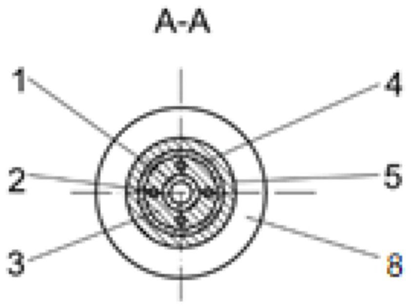
The invention provides an optical fiber line structure unit, which includes a metal bellows wrapped around the optical fiber from inside to outside, several carbon steel wires, stainless steel mesh, and an outer tube, and elastic supports are filled between the metal bellows and the outer tube material, one end of the outer tube is provided with a plug, the first clamping sleeve, and the other end of the outer tube is provided with a joint and a second clamping sleeve, and one end of the joint is inserted into the stainless steel mesh, and then passes through the second clamping sleeve Fixed, the other end of the joint is provided with a retaining ring and a sealing ring. The present invention also provides an optical fiber line, which includes several optical fiber line structural units connected end to end in sequence, and the metal bellows controlling the optical fiber line has an uninterrupted structure consistent with the optical fiber. The optical fiber line of the present invention provides sufficient protection for the optical fiber, the length can be designed, and the applicability is high; it can be bent to a certain degree and maintain a stable posture, and at the same time has a good vibration reduction effect, stretch resistance, waterproof, insulation, wear resistance, Easy to use.

Description

technical field [0001] The invention relates to the technical field of optical fiber protection devices, in particular to an optical fiber line structural unit and an optical fiber line. Background technique [0002] In the current laser transmission, the optical fiber is widely used because it can change the transmission direction of the optical path arbitrarily. However, under different bending postures inside the fiber, the internal stress of the structure is different, so it will have a certain impact on the transmission of polarized laser light. [0003] Armored optical fiber is to wrap a layer of protective "armor" on the outside of the optical fiber, which is mainly used to meet the requirements of customers to prevent rat bites and moisture. However, the existing optical fiber armor can only protect and seal the optical fiber to a certain extent, and its shape is very soft and cannot maintain a stable posture. Due to the limited working mechanism and process condit...

Claims


Application Information

Patent Timeline
Patent Type & Authority Patents(China)
IPC IPC(8): G02B6/44
CPCG02B6/443
Inventor 周嘉祺陈兆兵徐新行王恒坤时魁
Owner CHANGCHUN INST OF OPTICS FINE MECHANICS & PHYSICS CHINESE ACAD OF SCI
Why Eureka
Eureka Blog
Learn More