Full-automatic centre for take-up and pay-off stands of optical cable stranding machines

A twisting machine, winding and unwinding technology, applied in the field of fully automatic top, can solve the problems of prolonging the production time of optical cables, reducing the production efficiency, and difficult for operators, and achieving the advantages of reducing the operation time of changing the disc, improving the production efficiency and accurate detection. Effect

Inactive Publication Date: 2016-12-07
ANHUI UNIV OF SCI & TECH
View PDF8 Cites 0 Cited by
  • Summary
  • Abstract
  • Description
  • Claims
  • Application Information

AI Technical Summary

Problems solved by technology

[0002] Stranding machine is an essential stranding equipment in the manufacturing process of layer-stranded optical cables such as OPGW. During the use of the stranding machine, the steel wire reel and steel pipe reel must be replaced frequently on the take-up and pay-off rack. The traditional take-up and pay-off rack uses The most common method is manual operation, relying entirely on the hard work of the operator to unscrew the tip, unload the tray, load the tray, re-tighten the tip, etc., and because each stranding machine contains 12 or 16 take-up and pay-off racks, each time the steel wire is replaced When using coils and steel coils, it brings difficulties and dangers to operators, and also prolongs the production time of optical cables and greatly reduces production efficiency.

Method used


Image

  • Full-automatic centre for take-up and pay-off stands of optical cable stranding machines

Examples


Embodiment Construction

[0011] Below in conjunction with accompanying drawing, the present invention is described in detail:

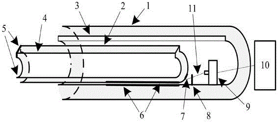
[0012] Such as figure 1 As shown in the figure, a fully automatic top for the take-up and release rack of an optical cable stranding machine includes a top 1, and the top 1 contains a solid disk bearing 2, a solid-slip groove 3, a solid-slip convex groove 4, and a front pressure Sensor 5, gear guide rail 6, post-stage pressure sensor 7, shrink cut-off line 8, retractable motor 9, motor controller 10 and wire 11.

[0013] The top 1 adopts a stainless steel cylindrical structure and is installed on each take-up and release rack of the optical cable stranding machine. The inner layer is designed as a cylindrical hollow with a diameter of 0.82 meters and a wall thickness of 0.06 meters. The top of the inner layer contains a solid-slip groove 3. The bottom end contains a 0.06-meter-long gear guide rail 6 and a shrinkage cut-off line 8, and is fixed with a retractable motor 9; the...


PUM


Abstract

The invention provides a full-automatic centre for take-up and pay-off stands of optical cable stranding machines, and belongs to the field of manufacturing equipment of optical cables. The full-automatic centre comprises a centre body 1, and the centre body 1 is provided with a fixed plate bearing 2, a fixed sliding concave groove 3, a fixed sliding convex groove 4, a front-stage pressure sensor 5, a gear guide rail 6, a rear-stage pressure sensor 7, a contractible cutting-off line 8, a take-up and pay-off motor 9, a motor controller 10 and a wire 11. Field installation test results of the full-automatic centre show that motor control is stable, the fixed plate bearing can be freely contracted and slightly adjusted, detection by the sensors is accurate, the protective capability is high, the plate change operation time can be greatly shortened, the workload of operators can be reduced, the production efficiency of optical cables can be improved, and therefore the full-automatic centre is suitable for being popularized and applied on the take-up and pay-off stands of the optical cable stranding machines.

Description

technical field [0001] The invention belongs to the field of optical cable manufacturing equipment, and in particular relates to a fully automatic tip used for a take-up and release rack of an optical cable stranding machine. Background technique [0002] Stranding machine is an essential stranding equipment in the manufacturing process of layer-stranded optical cables such as OPGW. During the use of the stranding machine, the steel wire reel and steel pipe reel must be replaced frequently on the take-up and pay-off rack. The traditional take-up and pay-off rack uses The most common method is manual operation, relying entirely on the hard work of the operator to unscrew the tip, unload the tray, load the tray, re-tighten the tip, etc., and because each stranding machine contains 12 or 16 take-up and pay-off racks, each time the steel wire is replaced When using reels and steel pipe reels, it brings difficulties and dangers to operators, and at the same time prolongs the prod...

Claims


Application Information

Patent Timeline
Patent Type & Authority Applications(China)
IPC IPC(8): B65H75/44
CPCB65H75/44B65H75/4486B65H2551/15B65H2551/20B65H2551/24B65H2553/80B65H2701/32
Inventor 朱艳娜何刚缪佳颖饶蓓蕾
Owner ANHUI UNIV OF SCI & TECH
Why Eureka
Try Eureka