Heat treatment unit with a pair of linear furnaces and slip rings

A heat treatment device and linear technology, applied in heat treatment furnaces, heat treatment equipment, furnaces, etc., can solve problems such as unqualified product shape and product quality decline, and achieve the effect of improving product quality and preventing temperature deviation

Inactive Publication Date: 2018-07-06
POHANG IRON & STEEL CO LTD
View PDF8 Cites 0 Cited by
  • Summary
  • Abstract
  • Description
  • Claims
  • Application Information

AI Technical Summary

Problems solved by technology

This temperature deviation will lead to unqualified product shape and even lead to the problem of product quality decline

Method used


Image

  • Heat treatment unit with a pair of linear furnaces and slip rings
  • Heat treatment unit with a pair of linear furnaces and slip rings
  • Heat treatment unit with a pair of linear furnaces and slip rings

Examples


Embodiment Construction

[0024] Hereinafter, the present invention will be described in detail with reference to the accompanying drawings as examples. It should be noted that when components in each drawing are denoted by reference symbols, the same components in different drawings are denoted by the same symbols as much as possible. In addition, when describing the present invention, if it is considered that the detailed description of related known structures or functions will obscure the gist of the present invention, the detailed description will be omitted.

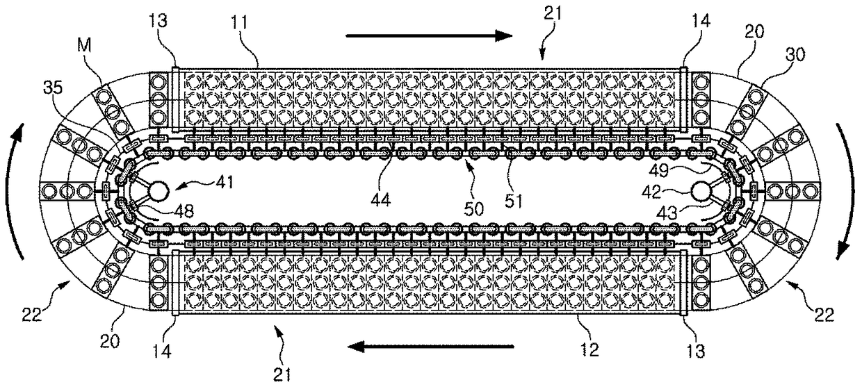
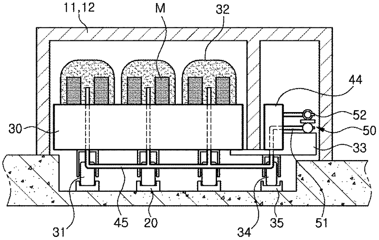
[0025] figure 1 is a plan view schematically showing a heat treatment apparatus according to a first embodiment of the present invention, figure 2 yes figure 1 A cross-sectional view of the heat treatment apparatus is shown.

[0026] as stated figure 1 and figure 2 As shown, the heat treatment device of the first embodiment of the present invention includes: a first linear furnace 11 and a second linear furnace 12, respectively havin...


PUM


Abstract

The invention relates to a heat treatment device, which is characterized in that it comprises: a first linear furnace and a second linear furnace, respectively having an input end and a discharge end; crawlers, which run through the first linear furnace and the second connected to the linear furnace; at least one trolley, which moves along the crawler belt, can pass through the first linear furnace and the second linear furnace, and load the material to be processed; and a gas supply part, which is connected to the table The car is connected and supplied with gas. Therefore, the present invention can eliminate the area for supplying excess heat, effectively use heat energy, and prevent temperature deviation, thereby further improving product quality.

Description

technical field [0001] The present invention relates to a heat treatment device equipped with a pair of linear furnaces and a collector ring (ring header), and more specifically relates to a device that can reduce heat loss and prevent temperature deviation compared with curved furnaces, thereby improving product quality. A pair of linear furnaces and a heat treatment unit for slip rings. Background technique [0002] For example, a heat treatment device for steel plates loads materials to be processed (for example, coils, etc.) on the floor of a trolley running on a circular crawler, covers it with a muffle furnace, and conveys it in a ring-shaped furnace. [0003] The ring furnace has a heating zone with loading doors and a cooling zone with recovery doors. In the furnace, the trolley moves section by section, so that the material to be processed is heated to a specified temperature in the heating area, and the temperature is maintained. Afterwards, when the material to ...

Claims


Application Information

Patent Timeline
Patent Type & Authority Patents(China)
IPC IPC(8): C21D1/00C21D9/00
Inventor 施性奎全知娟尹思源郑昌规
Owner POHANG IRON & STEEL CO LTD
Why Eureka
Try Eureka