Gradient type ring blowing cooling device for ultra-high speed spinning of polylactic acid staple fiber

A polylactic acid short fiber, ultra-high-speed spinning technology, applied in the field of synthetic fiber production equipment, can solve the problems of increased energy consumption, increased cold air volume and wind speed, fiber winding, etc., and achieve the effect of meeting the requirements of rapid cooling

Active Publication Date: 2018-03-09
CHANGSHU GOLD SPRING CHEM FIBERS & KNITTINGS
View PDF18 Cites 2 Cited by
  • Summary
  • Abstract
  • Description
  • Claims
  • Application Information

AI Technical Summary

Problems solved by technology

However, practice has proved that this method is not advisable, because when the temperature of the cold air from the air conditioner is excessively reduced, it will cause quenching to the spinneret of the structural system of the spinning assembly, thereby causing differences in fiber sheath and core due to quenching increase, the strands will become stiff, the hand feel will deteriorate, and the quality of the fiber will be affected; and because the air volume and wind speed of the cold air per unit time will be increased blindly, it will cause the divergence of the tow, the fiber flutter, the fiber linear density and the CV value. increase, and even cause the fibers to entangle with each other, which cannot be produced normally, and will cause an increase in energy consumption

Method used


Image

  • Gradient type ring blowing cooling device for ultra-high speed spinning of polylactic acid staple fiber
  • Gradient type ring blowing cooling device for ultra-high speed spinning of polylactic acid staple fiber

Examples


Embodiment Construction

[0024] In order to understand the technical essence and beneficial effects of the present invention more clearly, the applicant will describe in detail the following in the form of examples, but the description of the examples is not to limit the solution of the present invention. Equivalent transformations that are only formal but not substantive should be regarded as the scope of the technical solution of the present invention.

[0025] In the following descriptions, all concepts involving directionality or orientation of up, down, left, right, front and rear are aimed at figure 1As far as the position state shown is concerned, it cannot be understood as a special limitation on the technical solution provided by the present invention.

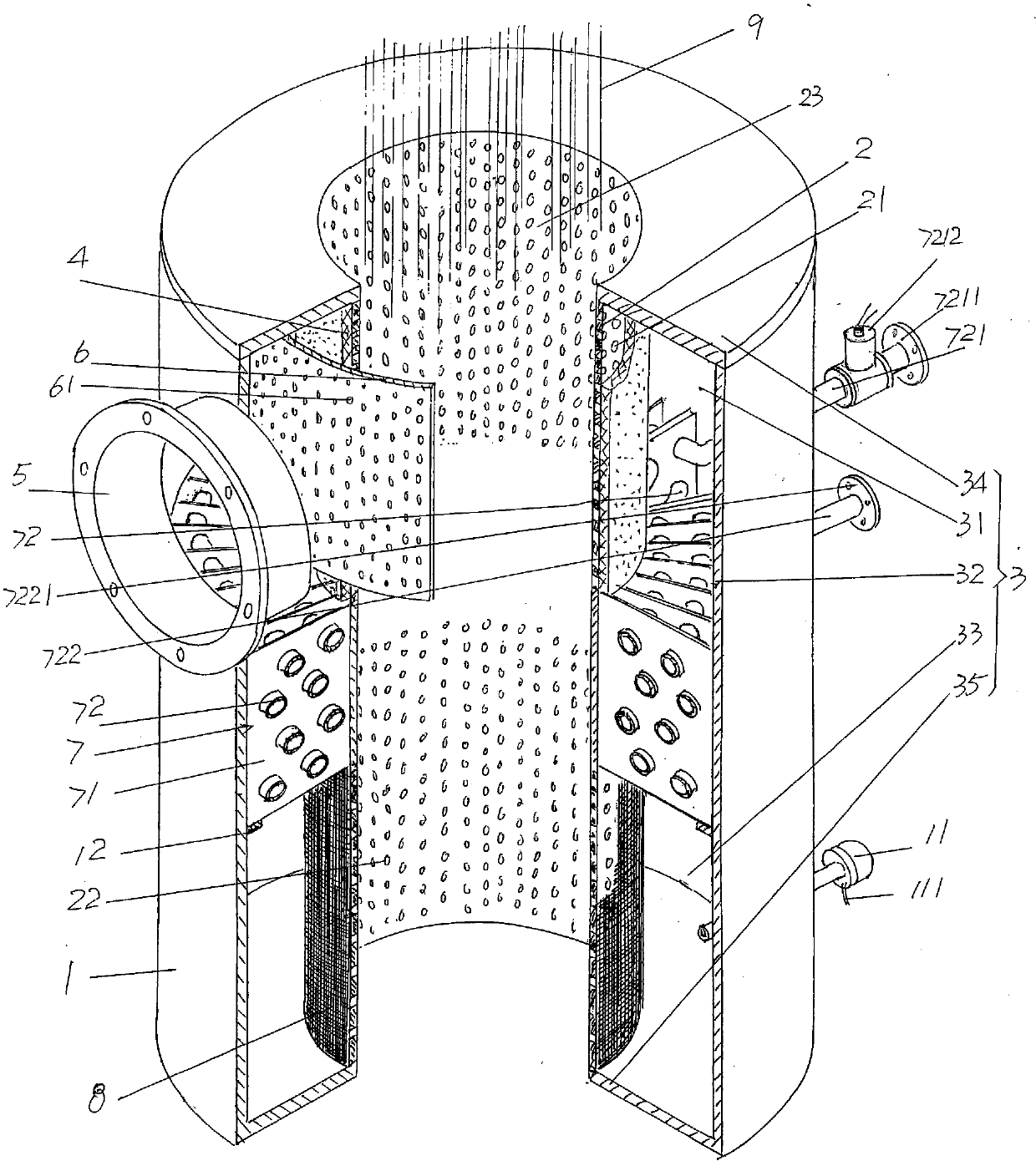
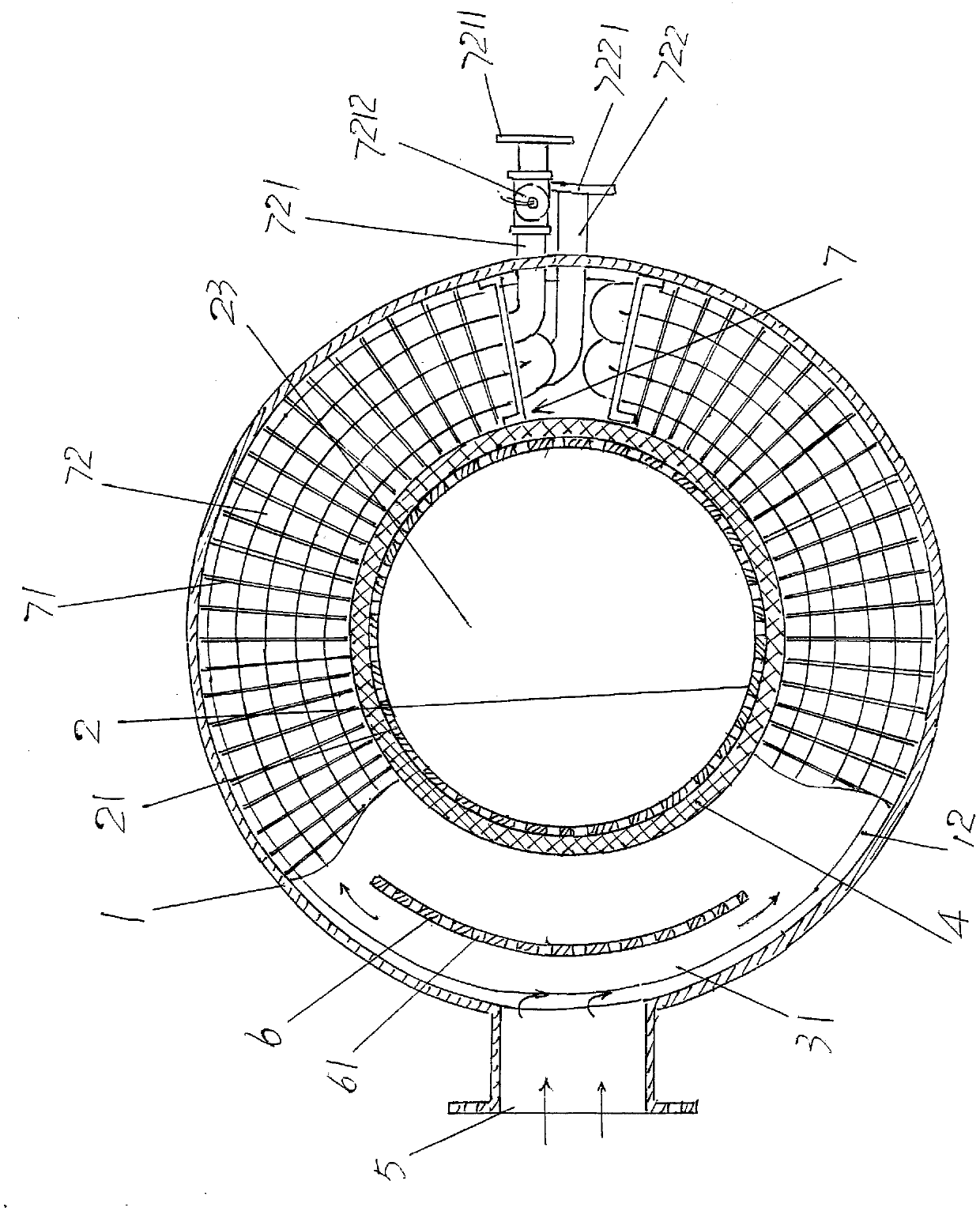
[0026] See figure 1 and figure 2 , showing a cooling cylinder 1 and a flow guide inner sleeve 2, the cooling cylinder 1 is set under the spinneret corresponding to the spinning assembly of the spinning machine in the use state, specificall...


PUM


Abstract

Provided is a gradient circular blowing cooling device used for polylactic acid short-fiber super-high speed spinning, pertaining to the technical field of synthetic fiber production equipment. The device comprises a cooling drum and a flow-guide inner sleeve. The cooling drum is arranged below a spinneret plate. The flow-guide inner sleeve is arranged in the cooling drum and a sleeve separation cavity is arranged on the inner wall of the cooling drum. The upper part of the sleeve separation cavity is an upper cooling cavity. The middle of the sleeve separation cavity is a surface air cooler cavity. The lower part of the sleeve separation cavity is a lower cooling cavity. The device further comprises a filter sleeve and a surface air cooler, as well as a filter net sleeve. The filter sleeve is arranged in the upper cooling cavity. An air-conditioning wind import interface is fixed on the cooling drum and communicates with the upper cooling cavity. A flow distribution plate is arranged in the upper cooling cavity and fixed with one side, upwardly facing the upper cooling cavity, of a top sealing cover of a sleeve separation cavity. Ventilation holes are arranged in the flow distribution plate. The surface air cooler is arranged between the cooling drum and the flow-guide inner sleeve and connected with a cooling water circulation heat-exchanging device. The filter net sleeve is arranged in a lower cooling cavity. Therefore, the spinneret plate can be used for smoothly extruding polylactic acid melt filaments in order to meet the rapid cooling requirement for acid melt filaments. Therefore, super-high speed spinning can be carried out.

Description

technical field [0001] The invention belongs to the technical field of synthetic fiber production equipment, and in particular relates to a gradient type ring blowing cooling device for ultra-high-speed spinning of polylactic acid short fibers. Background technique [0002] Known melt spinning is to extrude the high polymer spinning melt such as PA and / or PE from the spinneret holes of the spinneret of the spinning machine, and the extruded melt fine stream is cooled, Stretching, and finally solidified into filaments, the filaments are used as raw filaments for post-spinning and drafting or other purposes. During the spinning process, the polymer spinning melt is extruded from the spinneret hole of the spinneret of the spinning machine until it is wound by the winding device through the flow deformation zone, the orientation crystallization zone and the plastic deformation zone. [0003] As is known in the industry, because the fine and dense melt filaments just extruded fr...

Claims


Application Information

Patent Timeline
Patent Type & Authority Patents(China)
IPC IPC(8): D01D5/092
CPCD01D5/092
Inventor 樊海彬王维平杨新华
Owner CHANGSHU GOLD SPRING CHEM FIBERS & KNITTINGS
Why Eureka
Try Eureka