Bridge rotating construction rotating spherical hinge with self-centering function

A self-centering and spherical hinge technology, which is applied in bridges, bridge construction, erection/assembly of bridges, etc., can solve the problems of low bearing capacity of concrete hinges, uneven force, and few applications, so as to improve construction convenience and reliability performance, shorten the manufacturing period, and optimize the effect of the spherical joint structure

Active Publication Date: 2016-12-07
LUOYANG SUNRUI SPECIAL EQUIP +1
View PDF6 Cites 6 Cited by
  • Summary
  • Abstract
  • Description
  • Claims
  • Application Information

AI Technical Summary

Problems solved by technology

[0003] The swivel uses concrete hinges, swivel flat hinges and swivel spherical hinges as the rotating components. Among them, the concrete hinges have low bearing capacity, large structure, and large friction coefficient, which are not suitable for large-tonnage swivel bridges.
The structure of the swivel flat hinge has poor rigidity, uneven force, poor centering performance, and easy to get stuck when rotating, so it is rarely used.

Method used


Image

  • Bridge rotating construction rotating spherical hinge with self-centering function
  • Bridge rotating construction rotating spherical hinge with self-centering function
  • Bridge rotating construction rotating spherical hinge with self-centering function

Examples


Embodiment Construction

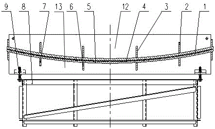
[0012] As shown in the figure, a swivel spherical joint for bridge swivel construction with self-centering function, including an upper spherical joint, a lower spherical joint, and a non-metallic slide plate with a multi-layer structure.

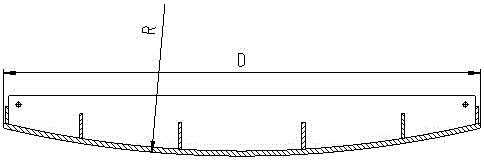
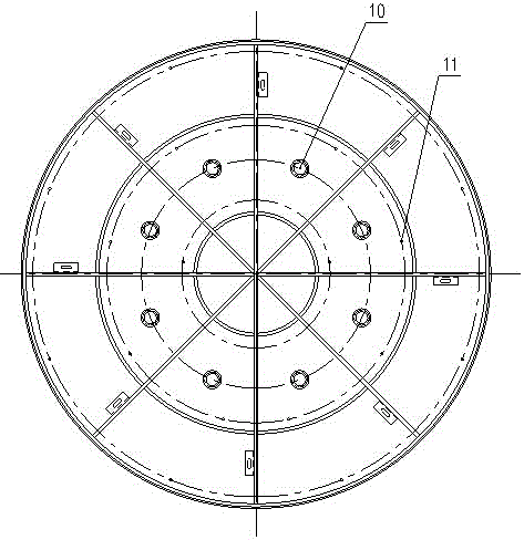
[0013] The upper spherical hinge includes an upper spherical hinge spherical panel and an upper spherical hinge rib plate, and the upper spherical hinge spherical panel is a convex spherical surface; the upper spherical hinge spherical panel is a complete structure without opening a hole in the center of the spherical hinge , the inner side of the upper ball hinge spherical panel has several radially arranged ribs and several annular (polygonal) ribs, and the radial ribs and annular (polygonal) ribs are welded to each other and welded to the upper ball hinge spherical panel above, forming a frame structure.

[0014] The lower ball hinge includes a lower ball hinge spherical panel and a lower spherical hinge rib plate, and the lower spherica...


PUM


Abstract

Provided is a bridge rotating construction rotating spherical hinge with a self-centering function. An upper spherical hinge convex spherical surface is matched with a lower spherical hinge concave spherical surface. Automatic positioning of a structure is achieved under the effect of the self weight and vertical loads, intermediate hinge pins are not arranged, the machining, manufacturing and assembling cost is saved, the manufacturing period is shortened, and the situation that hinge pins are stuck in the rotating process is avoided. Through improvement of the spherical hinge structure, the structural rigidity of the spherical hinge is improved, the spherical hinge can be conveniently mounted, the requirement for rotating construction of a high-bearing bridge structure is met, and construction convenience and reliability are improved.

Description

technical field [0001] The invention relates to the technical field of bridge engineering, and relates to a structural device used in the construction of a bridge by a swivel method, capable of bearing vertical loads and realizing the swivel of the bridge by self-positioning along the structure centroid. Background technique [0002] Bridge construction often needs to cross places such as railways, highways, canyons, etc. Due to the constraints of transportation or the inability to construct above them, these places must be constructed by prefabricating beams. At present, the construction of this type of bridge mainly adopts the beam body horizontal push or swivel construction method. The beam body horizontal push construction is divided into two types: horizontal push and vertical push. Both methods need to build temporary piers and temporary slides. On the slider, the slider is connected to the tension jack on the opposite side through a wire rope, and the beam body is slo...

Claims


Application Information

Patent Timeline
Patent Type & Authority Applications(China)
IPC IPC(8): E01D21/08
CPCE01D21/08
Inventor 李新郑娜宋建平何平根
Owner LUOYANG SUNRUI SPECIAL EQUIP
Why Eureka
Try Eureka