Lateral-clamping vibration hammer

A vibratory hammer and side clamping technology, applied in construction, sheet pile walls, foundation structure engineering, etc., can solve the difficulty of picking up piles, affect the flexibility and stability of excavator piling, and make it difficult for the clamping device to lie down on the pile and problems such as driving inclined piles

Active Publication Date: 2016-12-07
WENZHOU ZHENZHONG FOUND CONSTR MASCH TECH CO LTD
View PDF5 Cites 4 Cited by
  • Summary
  • Abstract
  • Description
  • Claims
  • Application Information

AI Technical Summary

Problems solved by technology

[0002] In the prior art, the vibratory hammer includes a vibration damping device, a vibration device, a clamping device, and a driving device. The clamping device cannot rotate 360º due to the entanglement of the oil pipe, making it difficult for the clamping device to clamp the pile body. At the same time, the pile body The flexibility of moving and positioning is poor; at the same time, because the clamping device cannot rotate longitudinally relative to the lifting device, it is difficult to rely on the clamping device to lie down and drive the pile, and the clamping device has different orientations on the piles arranged on the ground. Difficult to grasp
[0003] The clamping device of the vibratory hammer includes a chuck body, which is used to clamp the upper end of the sheet pile or steel pipe pile. However, when the pile body is long, a large-tonnage excavator and the main arm and auxiliary of the excavator are required. The length of the arm is modified, which increases the market entry threshold for excavators used for piling, and affects the flexibility and stability of excavators for piling

Method used


Image

  • Lateral-clamping vibration hammer
  • Lateral-clamping vibration hammer
  • Lateral-clamping vibration hammer

Examples


Embodiment Construction

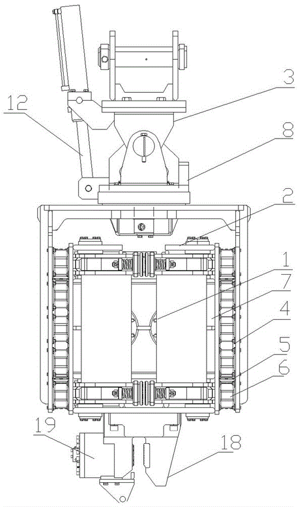
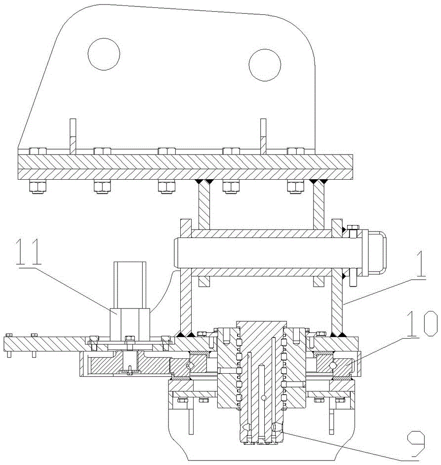
[0017] Accompanying drawing has shown structure of the present invention, further illustrates its relevant details below again in conjunction with accompanying drawing. This side clip vibratory hammer comprises vibrating device 1, clamping device 2, hoisting device 3 and control system, and hoisting device comprises the structure such as boom as prior art, and control system can be programmable logic controller PLC, and described vibrating device 1 is connected with the clamping device 2, the clamping device 2 and the vibrating device 1 are arranged in the vibration damping device 4, the vibration damping device 4 includes an outer frame 5 and a rubber spring 6 arranged on the inner wall of the outer frame 5, the rubber spring 6 is connected with the vibration box 7, the vibration box 7 is used to install the vibration device 1, a rotating body 8 is arranged above the vibration damping device 4, and a central rotary joint 9 and a rotating body are connected between the vibratio...


PUM


Abstract

The invention discloses a lateral-clamping vibration hammer, which comprises a vibration device, a clamping device, a lifting device and a control system, and is characterized in that the clamping device and the vibration device are arranged in a vibration damping device; a rotating body is arranged above the vibration damping device; a central swivel joint and a pivoting support are connected between the vibration damping device and the rotating body; the vibration damping device can rotate for 360 degrees; the rotating body can be longitudinally hinged onto the lifting device rotatably; the clamping device comprises vibration box bodies, a left clamping arm and a right clamping arm; the left clamping arm and the right clamping arm are separately hinged onto the vibration box bodies; the clamping front end of the left clamping arm and the clamping front end of the right clamping arm are separately provided with a clamping plate; the rear end of each clamping plate is an arc surface; the clamping front end of each clamping arm is provided with a groove matched with the arc surface; each arc surface is rotatably arranged in the corresponding groove; an elastic piece is arranged in each clamping arm; each elastic piece is connected with the corresponding clamping plate; and the lower end of each vibration box body is also provided with a chuck. The lateral-clamping vibration hammer disclosed by the invention is reasonable in structure, is convenient for clamping a pile body, enabling the pile body to lie down and driving inclined pile and is stable in clamping.

Description

technical field [0001] The invention relates to an improved invention of an engineering vibratory hammer, in particular to an improved invention of a side clamp vibratory hammer. Background technique [0002] In the prior art, the vibratory hammer includes a vibration damping device, a vibration device, a clamping device, and a driving device. The clamping device cannot rotate 360º due to the entanglement of the oil pipe, making it difficult for the clamping device to clamp the pile body. At the same time, the pile body The flexibility of moving and positioning is poor; at the same time, because the clamping device cannot rotate longitudinally relative to the lifting device, it is difficult to rely on the clamping device for lying down and driving inclined piles, and the clamping device is not suitable for piles arranged on the ground in different orientations. Gripping is difficult. [0003] The clamping device of the vibratory hammer includes a chuck body, which is used t...

Claims


Application Information

Patent Timeline
IPC IPC(8): E02D7/18
CPCE02D7/18
Inventor 曹高峻谢作荣林光杰
Owner WENZHOU ZHENZHONG FOUND CONSTR MASCH TECH CO LTD
Why Eureka
Try Eureka