Eureka AIR delivers breakthrough ideas for toughest innovation challenges, trusted by R&D personnel around the world.

Lifting type climbing ladder

A technology for climbing ladders and ontology, applied in ladders, elevators, buildings, etc., can solve the problems of small shaft size, difficulty in leaving the pit, and small distances

Active Publication Date: 2016-12-07
HITACHI ELEVATOR CHINA
View PDF6 Cites 8 Cited by
  • Summary
  • Abstract
  • Description
  • Claims
  • Application Information

AI Technical Summary

Problems solved by technology

[0002] The pit ladder device of traditional elevators is a special device for operators to safely enter and exit the pit. In the prior art, when the ladder is arranged on the inner wall of the well on the side of the landing door, the well space required by some elevators is relatively small. Large, personnel may still not be able to safely touch the floor door lock device through the ladder, making it difficult for personnel to leave the pit
[0003] According to the current competition trend of the elevator market, the size of the elevator shaft and the depth of the pit are required to be as small as possible, so that the arrangement of the elevator components in the shaft is as compact as possible, so some vertical elevators with small shaft sizes and cannot be installed with side ladders ( Such as machine room-less elevators, because the side-mounted ladders are easy to interfere with the shaft parts), the pit ladders can only be fixedly installed directly under the sill of the hall door on the first floor; When the operator enters the pit, the distance between the ladder pedal and the inner wall of the hoistway is very small, which is prone to the danger of personnel slipping into the pit and being injured

Method used


Image

  • Lifting type climbing ladder
  • Lifting type climbing ladder
  • Lifting type climbing ladder

Examples


Embodiment Construction

[0039] In order to make the object, technical solution and advantages of the present invention clearer, the present invention will be further described in detail below in conjunction with the accompanying drawings and specific implementation methods. It should be understood that the specific embodiments described here are only used to explain the present invention, and do not limit the protection scope of the present invention.

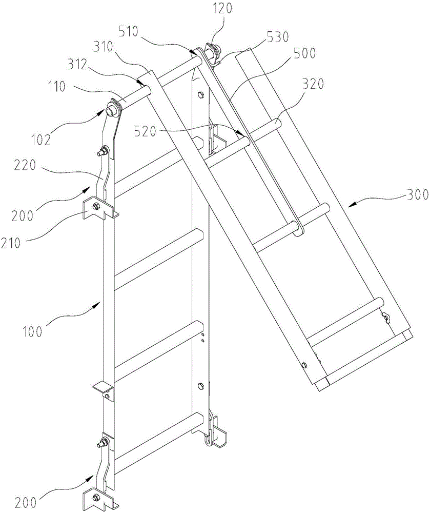
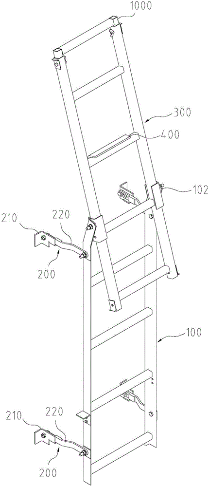
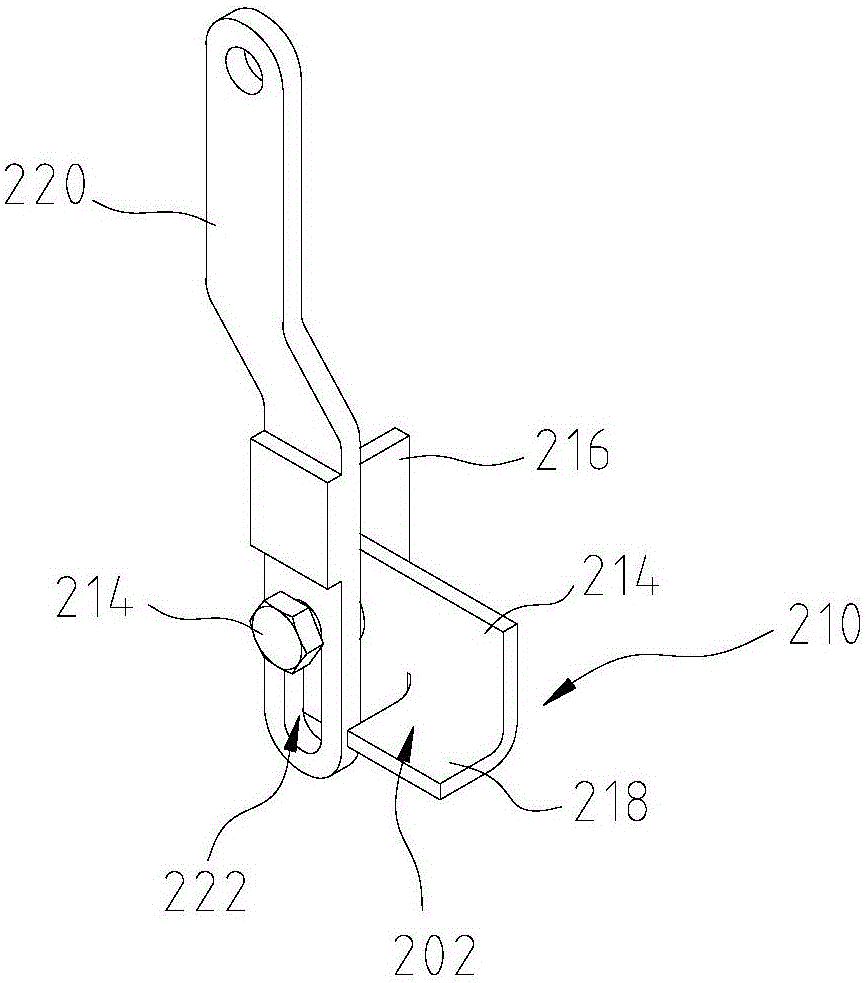
[0040] Such as Figures 1 to 5As shown, a pull-type ladder according to the present invention includes a first ladder body 100, the first ladder body 100 includes a first end 102; at least one pair of connecting mechanisms 200, at least one pair of connecting mechanisms 200 are respectively arranged on the second On both sides of a ladder body 100, the connection mechanism 200 includes a support 210 and a connecting rod 220. The support 210 is used to be fixed at a preset fixed position. The support 210 is provided with a limiter. 210 is movably conn...


PUM


Abstract

The invention relates to a lifting type climbing ladder, which comprises a first climbing ladder body, at least one pair of connecting mechanisms and a second climbing ladder body, wherein the first climbing ladder body comprises a first end; the at least one pair of connecting mechanisms is respectively arranged at the two sides of the first climbing ladder body; each connecting mechanism comprises a support seat and a connecting rod element; the support seat is used for fixing the preset fixing position; the support seat is provided with a position limiting part; one end of the connecting rod element is movably connected with one end of the support seat, and can rotate and / or slide relative to the support seat; the other end of the connecting rod element is rotationally connected with the first climbing ladder body; when the connecting rod element rotates to the preset position, the connecting element is clamped and fixed with the position limiting part; one end of the second climbing ladder body is movably connected with the first end of the first climbing ladder body, and can rotate or / and slide relative to the first climbing ladder body; the second climbing ladder body is provided with a locking mechanism capable of being fixed with a ground sill. The lifting type climbing ladder can be arranged in a hoistway bottom pit with small dimension; operators can conveniently go in or go out of the bottom pit.

Description

technical field [0001] The invention belongs to the technical field of elevators, and particularly relates to a climbing ladder, in particular to a pull-type climbing ladder installed in an elevator shaft for safe entry and exit from a bottom pit. Background technique [0002] The pit ladder device of traditional elevators is a special device for operators to safely enter and exit the pit. In the prior art, when the ladder is arranged on the inner wall of the well on the side of the landing door, the well space required by some elevators is relatively small. Large, personnel may still not be able to safely touch the floor door lock device through the ladder, making it difficult for personnel to leave the pit. [0003] According to the current competition trend of the elevator market, the size of the elevator shaft and the depth of the pit are required to be as small as possible, so that the arrangement of the elevator components in the shaft is as compact as possible, so som...

Claims


Application Information

Patent Timeline
IPC IPC(8): E06C9/08E06C7/48E06C7/50E06C7/00E06C7/02E06C7/04E06C7/06B66B5/00
CPCB66B5/0087E06C7/00E06C7/02E06C7/04E06C7/06E06C7/482E06C7/50E06C9/08E06C9/085
Inventor 范仲华陈程李淑钰
Owner HITACHI ELEVATOR CHINA
Why Eureka
Eureka Blog
Learn More