Ribbed beam type closed cutting U-shaped groove structure
A U-shaped groove and rib beam technology, applied in infrastructure engineering, roads, roads, etc., can solve the problems of low material utilization rate, large amount of technical engineering, increased groundwater buoyancy and water and soil pressure.
Pending Publication Date: 2020-10-30
BEIJING GENERAL MUNICIPAL ENG DESIGN & RES INST
View PDF0 Cites 1 Cited by
- Summary
- Abstract
- Description
- Claims
- Application Information
AI Technical Summary
Problems solved by technology
The existing technology usually adopts the method of increasing the thickness of the structural floor and side wall to offset the influence of groundwater buoyancy and water and soil pressure, but increasing the thickness of the floor will lead
Method used
View moreImage
Smart ImageViewing Examples

Examples
 PUM
 Abstract
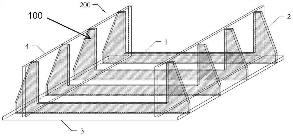
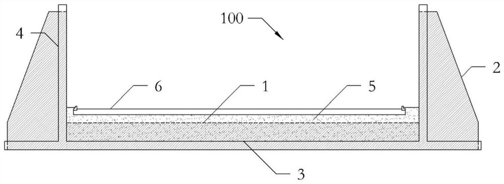
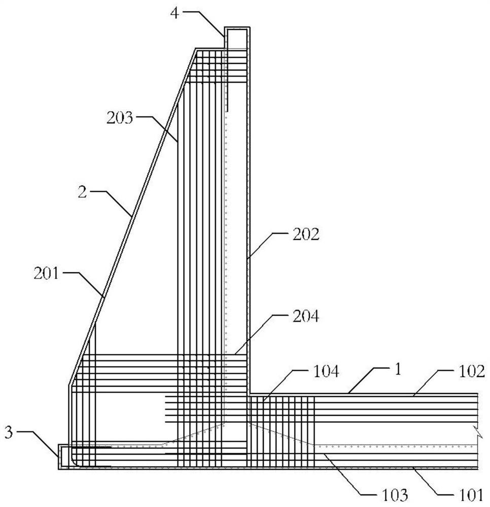
A ribbed beam type closed cutting U-shaped groove structure comprises a side wall, a bottom plate, a balance weight pavement layer and a pavement structure. The side wall is provided with a vertical side wall ribbed beam, the bottom plate is provided with a horizontal bottom plate ribbed beam, and the side wall ribbed beam and the two ends of the bottom plate ribbed beam are integrally connected to form a U-shaped ribbed beam. The multiple U-shaped ribbed beams are arranged in parallel at equal intervals in a direction perpendicular to a road center line. The side wall and the bottom plate arethin plates and are thinner than the side wall ribbed beam and the bottom plate ribbed beam; the side wall ribbed beams are connected into an integrated structure through the side wall, and the bottom plate ribbed beams are connected into an integrated structure through the bottom plate; and the U-shaped ribbed beams, the side wall and the bottom plate are poured into a closed reinforced concreteintegral structure through concrete. According to the structure, a double-reduction effect of concrete and steel bar consumption is achieved, and a technical method is provided for a near important and risk source structure control base elevation scheme.
Description
technical field [0001] The invention relates to the technical field of closed cutting construction engineering, and specifically provides a U-shaped trough structure of a rib-beam type closed cutting, which is suitable for cutting sections with high groundwater levels and belongs to the U-shaped trough structure of closed cuttings. Background technique [0002] The existing closed cut U-shaped groove structure is an integral structure composed of a reinforced concrete bottom plate and side wall panels, and the self-weight of the structural bottom plate, side wall panels and auxiliary facilities such as paving resists the buoyancy of groundwater. The existing technology usually adopts the method of increasing the thickness of the structural floor and side wall to offset the influence of groundwater buoyancy and water and soil pressure, but increasing the thickness of the floor will lead to a decrease in the base elevation, which will further increase the groundwater buoyancy a...
Claims
Login to View More Application Information
Patent Timeline
 IPC IPC(8): E01C3/00E02D31/12
CPCE01C3/00E02D31/12
Inventor 应伟强朱琳韩磊李东陈晖栗志杰杜传金齐萱郭彦彬宋鑫李晓龙王欣黎抒婕陈青王忠强聂奥祥杨思敏贾岩丁立亚赵逸宁陈娜
Owner BEIJING GENERAL MUNICIPAL ENG DESIGN & RES INST