Air entraining structure used for inner rotor cavity of compressor

A compressor rotor and compressor technology, which is applied to the components of the pumping device for elastic fluid, mechanical equipment, machines/engines, etc., can solve problems such as the difficulty of structural design, reduce the additional stress of the rotor, and achieve high reliability. , the effect of reducing the additional stress

Inactive Publication Date: 2016-12-07
AECC SHENYANG ENGINE RES INST
View PDF3 Cites 6 Cited by
  • Summary
  • Abstract
  • Description
  • Claims
  • Application Information

AI Technical Summary

Problems solved by technology

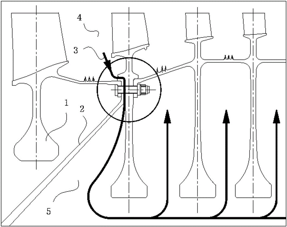
However, this also brings certain difficulties to the structural design. In the case of limited structural space, it is necessary to meet the reliability of the rotor connection structure and the air-bleeding requirements of the rotor cavity at the same time.

Method used


Image

  • Air entraining structure used for inner rotor cavity of compressor
  • Air entraining structure used for inner rotor cavity of compressor
  • Air entraining structure used for inner rotor cavity of compressor

Examples


Embodiment Construction

[0018] In order to make the objectives, technical solutions and advantages of the present invention clearer, the technical solutions in the embodiments of the present invention will be described in more detail below in conjunction with the drawings in the embodiments of the present invention. In the drawings, the same or similar reference numerals denote the same or similar elements or elements having the same or similar functions throughout. The described embodiments are some, but not all, embodiments of the invention. The embodiments described below by referring to the figures are exemplary and are intended to explain the present invention and should not be construed as limiting the present invention. Based on the embodiments of the present invention, all other embodiments obtained by persons of ordinary skill in the art without making creative efforts belong to the protection scope of the present invention. Embodiments of the present invention will be described in detail b...


PUM


Abstract

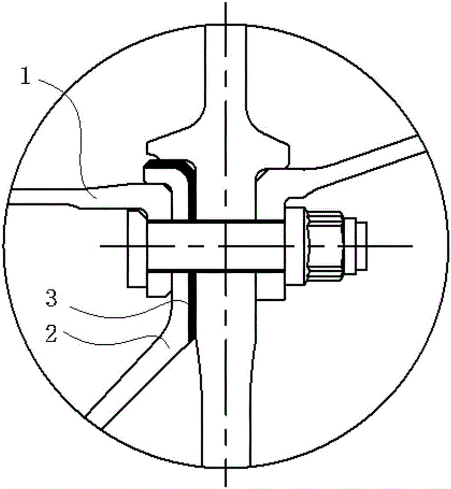
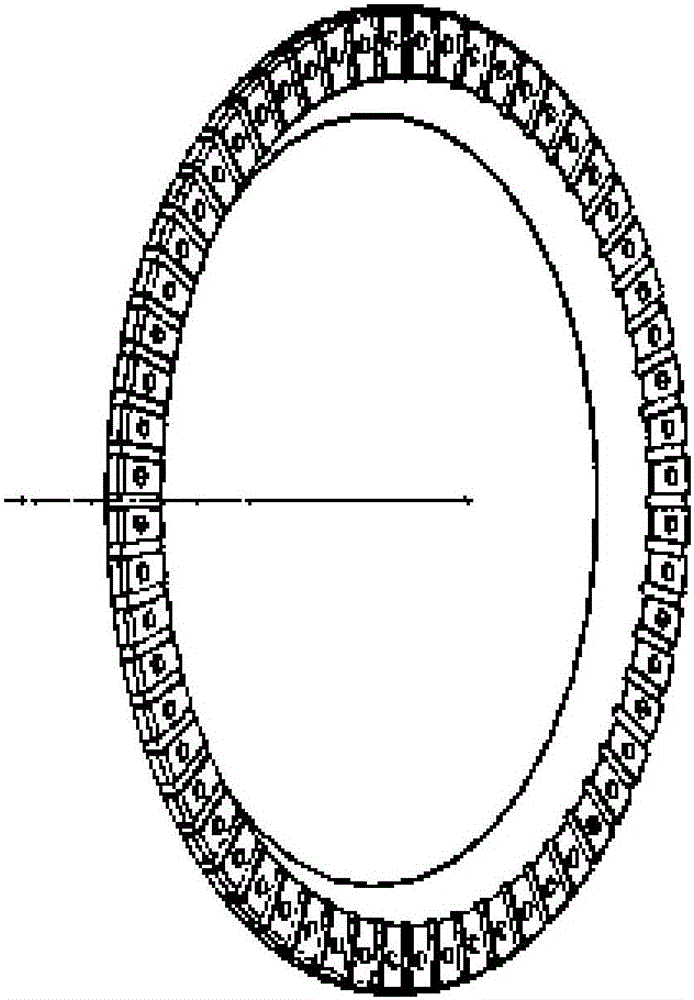
The invention relates to an air entraining structure used for an inner rotor cavity of a compressor. Multiple air entraining grooves are formed in the rotor installation edge of the compressor. Air entraining air flow communicates with the rotor inner cavity and an outer rotor cavity through the air entraining grooves. A compressor rotor, the rotor installation edge and a next level of compressor rotor are fixedly connected through a connecting piece. According to the air entraining structure used for the inner rotor cavity of the compressor, the air entraining air flow is entrained into the inner rotor cavity for heating a post level of inner rotor cavity of the compressor, the temperature gradient of a rotor disc is reduced, and therefore rotor additional stress brought by the temperature gradient is reduced; and in a limited structural space, safe and reliable connection of the rotor is not affected, air entraining of the inner rotor cavity is achieved while no extra structural part is arranged, the rotor additional stress, caused by the temperature gradient, on the rotor disc is reduced, the structure is safe, and reliability is high.

Description

technical field [0001] The invention belongs to the technical field of turbofan engines, and in particular relates to an air-bleed structure used in the inner cavity of a compressor rotor. Background technique [0002] With the development of turbofan engine design technology, the thrust-to-weight ratio of the turbofan engine increases, the pressure ratio of the compressor components gradually increases, and the temperature of the stage behind the compressor components also increases accordingly. This leads to the fact that the rotor in the rear stage of the compressor needs to bear the additional stress caused by the temperature gradient of the rotor while bearing high centrifugal load. However, due to the requirement that the weight of the engine be as light as possible, the stress of the rotor disk is difficult to meet the requirement of strength stress reserve under the requirement of light weight index. It is necessary to introduce hot air into the inner cavity of the ...

Claims


Application Information

Patent Timeline
Patent Type & Authority Applications(China)
IPC IPC(8): F04D29/28F04D29/58
CPCF04D29/286F04D29/582
Inventor 李惠莲曹铁男纪福森赵鑫
Owner AECC SHENYANG ENGINE RES INST
Why Eureka
Try Eureka