
Manual plunger valve device with upper valve seat body and lower valve seat body capable of being sealed independently

A plunger valve and valve seat technology, which is applied in the field of manual plunger valve devices, can solve the problems that the valve seat cannot be sealed separately, the lower valve stem is squeezed, etc., and achieve good guidance, small valve operating torque, and excellent friction performance Effect

Inactive Publication Date: 2016-12-07
SAILUOKE FLUID EQUIP INC
View PDF6 Cites 2 Cited by
  • Summary
  • Abstract
  • Description
  • Claims
  • Application Information

AI Technical Summary

Problems solved by technology

[0004] The technical problem to be solved by the present invention is that the valve seat in the upper half of the flow channel hole and the valve seat in the lower half of the flow channel hole cannot be sealed separately in the conventional structure, and the purpose is to provide a manual plunger valve device in which the upper and lower valve seats can be sealed separately , to solve the problem that both the valve seat in the upper half of the flow channel hole and the valve seat in the lower half of the flow channel hole need to be sealed, and it is difficult to guarantee it by squeezing the lower valve stem

Method used


Image

  • Manual plunger valve device with upper valve seat body and lower valve seat body capable of being sealed independently
  • Manual plunger valve device with upper valve seat body and lower valve seat body capable of being sealed independently

Examples


Embodiment 1

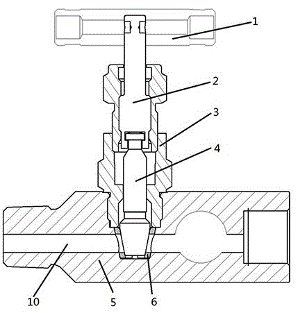
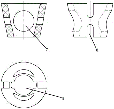
[0023] Such as figure 1 , figure 2 Shown is a manual plunger valve device in which the upper and lower valve seats can be sealed separately, including a handle 1, a bracket 3, a valve stem 4, a valve body 5, a flow channel 10, a push rod 2, and a valve seat 6; Turn the handle and connect to one end of the push rod 2 perpendicular to the axis of the push rod 2. The push rod 2 is 30cm long and 6cm in diameter. It is connected with the support 3 along the axis direction of the support 3 with a threaded structure. The support 3 is 50cm high and connected above the valve body 5. Vertical to the valve body 5, the valve body 5 is a cylindrical structure with a length of 60cm, an outer diameter of 20cm, and an inner diameter of 8cm. The length of the rod is 30cm and the diameter is 6cm. The end connecting the push rod 2 and the valve rod 4 is provided with a slotted hole. The draw-in groove cooperates with the draw-in shoot on the push rod 2, and the push rod 2 and the valve stem 4...


PUM


Abstract

The invention discloses a manual plunger valve device with an upper valve seat body and a lower valve seat body capable of being sealed independently. The manual plunger valve device comprises a handle, a support, a valve rod, a valve body and a runner and further comprises a push rod and a valve seat. The push rod is connected with the support through a thread structure, the guiding performance is good, and stability is high. The valve seat is made of PEEK materials and provided with a runner hole, a weakening hole and a plugging hole. The runner hole is formed in the runner axis direction of the valve seat. The plugging hole is formed in the valve rod axis direction. The weakening groove is formed in the direction perpendicular to the runner hole and the plugging hole. Due to the valve seat, the valve operation torque becomes small, and meanwhile the valve seat bodies above and below the runner hole can be locally sealed with the valve body independently. The manual plunger valve device has the beneficial effects that the valve is high in stability and good in guiding performance, the valve operation torque is small, and the valve seat bodies above and below the runner hole can be locally sealed with the valve body independently.

Description

technical field [0001] The invention relates to a plunger valve device, in particular to a manual plunger valve device whose upper and lower valve seats can be sealed separately. Background technique [0002] The plunger valve is a closing member or a plunger-shaped rotary valve. By rotating 90 degrees, the passage port on the valve plug communicates with or separates from the passage port on the valve body to realize opening or closing. The shape of the plunger valve plug can be cylindrical or conical. In cylindrical plugs, the passages are generally rectangular; in tapered plugs, the passages are trapezoidal. These shapes make the structure of the plunger valve light, but at the same time, it also produces a certain loss. The plunger valve is most suitable for cutting off and connecting the medium and dividing the flow, but it can also be used for throttling depending on the nature of the application and the erosion resistance of the sealing surface. The plunger valve u...

Claims


Application Information

Patent Timeline
Patent Type & Authority Applications(China)
IPC IPC(8): F16K5/02F16K5/08F16K5/16F16K31/60
CPCF16K5/02F16K5/0242F16K5/08F16K5/16F16K31/60
Inventor 付正凯
Owner SAILUOKE FLUID EQUIP INC
Learn More