Supercharge Your Innovation With Domain-Expert AI Agents!

A mobile adjustment device for camera

A technology of mobile adjustment and camera, which is applied in the direction of instruments, camera bodies, optics, etc., to achieve the effect of high definition and expanded application range

Active Publication Date: 2018-08-31
BEIJING COMPUTING CENT
View PDF7 Cites 0 Cited by
  • Summary
  • Abstract
  • Description
  • Claims
  • Application Information

AI Technical Summary

Problems solved by technology

[0005] The purpose of the present invention is to provide a mobile adjustment device for a camera to solve the problem in the prior art that when performing a measurement experiment of a three-dimensional flow field, multiple cameras are often needed, so it is necessary to be able to carry the movement of the camera. The adjustment device has multiple degrees of freedom

Method used


Image

  • A mobile adjustment device for camera
  • A mobile adjustment device for camera
  • A mobile adjustment device for camera

Examples


Embodiment Construction

[0031] The specific implementation manners of the present invention will be further described in detail below in conjunction with the accompanying drawings and embodiments. The following examples are used to illustrate the present invention, but are not intended to limit the scope of the present invention.

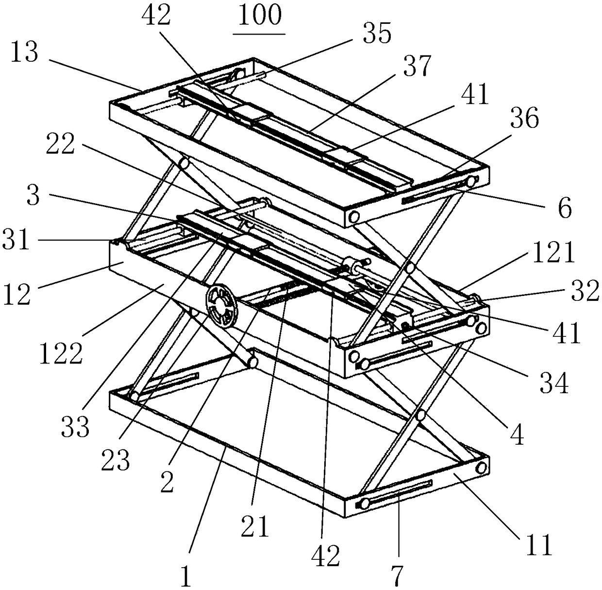
[0032] Such as figure 1 as shown, figure 1 It is schematically shown that the movement adjustment device 100 includes a lifting frame 1 , a vertical adjustment mechanism 2 , a front and rear adjustment mechanism 3 and a left and right adjustment mechanism 4 .

[0033] The lifting frame 1 includes a lower frame 11 , a middle frame 12 and an upper frame 13 which are movably connected sequentially from bottom to top. That is to say, the lower frame 11 , the middle frame 12 and the upper frame 13 can move toward or away from each other, so as to realize the overall lifting function of the lifting frame 1 .

[0034] The vertical adjustment mechanism 2 is arranged on the midd...


PUM


Abstract

The invention relates to the technical field of adjusting equipment of photographic instruments, and discloses a movable adjusting device used for a photographic instrument. The movable adjusting device used for the photographic instrument comprises a lifting framework, a vertical adjusting mechanism, front-back adjusting mechanisms and left-right adjusting mechanisms, wherein the lifting framework comprises a lower frame, a middle frame and an upper frame; the lower frame, the middle frame and the upper frame are sequentially and movably connected from bottom to top; the vertical adjusting mechanism is arranged on the middle frame and capable of adjusting the ascending and descending movement of the upper frame and the middle frame; the front-back adjusting mechanisms are arranged on the upper frame and the middle frame correspondingly and capable of adjusting the front and back movement of the photographic instrument; and the left-right adjusting mechanisms are arranged on the front-back adjusting mechanisms correspondingly and capable of adjusting the left and right movement of the photographic instrument. The movable adjusting device has the advantage that the photographic instrument can be adjusted in six degrees of freedom.

Description

technical field [0001] The invention relates to the technical field of camera adjustment equipment, in particular to a movement adjustment device for a camera. Background technique [0002] PIV (Ion Imaging Velocimetry) is a non-contact fluid velocimetry technology, through image correlation processing, to obtain the displacement of tracer particles in a short time, so as to indirectly measure the transient velocity distribution of the flow field. When the PIV system measures the flow field, it is necessary to adjust the positioning of the high-speed camera so that the tracer particles can form a clear image on each frame of the high-speed camera. [0003] Only one or two cameras are needed for two-dimensional PIV experiments, and at least two or four cameras are required for three-dimensional PIV experiments. However, when four cameras are used, the movement adjustment device capable of carrying the four cameras needs to have multiple degrees of freedom. Contents of the ...

Claims


Application Information

Patent Timeline
Patent Type & Authority Patents(China)
IPC IPC(8): G03B17/56F16M11/04F16M11/18
CPCF16M11/043F16M11/18G03B17/561
Inventor 翟奋楼孙鹏劼李娇娇刘彤李哲
Owner BEIJING COMPUTING CENT
Features
  • R&D
  • Intellectual Property
  • Life Sciences
  • Materials
  • Tech Scout
  • Unparalleled Data Quality
  • Higher Quality Content
  • 60% Fewer Hallucinations
Learn More