Gas backflow structure and air conditioner device with same

An air-conditioning device and gas technology, applied in air-conditioning systems, airflow control components, household appliances, etc., can solve problems such as difficult to achieve effects, user discomfort, and limited cooling effect, so as to improve cooling efficiency and reduce power consumption cost effect

Inactive Publication Date: 2016-12-07
MOAI ELECTRONICS
View PDF9 Cites 1 Cited by
  • Summary
  • Abstract
  • Description
  • Claims
  • Application Information

AI Technical Summary

Problems solved by technology

[0003] However, such wearable air-conditioning devices have obvious disadvantages. First, limited by the existing structure of the helmet, the cold air discharged from the helmet can only be blown to a very limited area, and it is difficult to spread it evenly over a large area. emissions, making the cooling effect quite limited
Secondly, the existing air conditioner only discharges cold air, and in order to discharge cold air at a certain temperature, the refrigeration mechanism must continue to operate at a certain level of load, which is prone to power c

Method used


Image

  • Gas backflow structure and air conditioner device with same
  • Gas backflow structure and air conditioner device with same
  • Gas backflow structure and air conditioner device with same

Examples


Example Embodiment

[0070] The implementation of the present invention is described below through specific specific examples, and those skilled in the art can easily understand other advantages and effects of the present invention from the content disclosed in this specification.

[0071]It should be noted that the structures, proportions, sizes, etc. shown in the drawings attached to this specification are only used to match the content disclosed in the specification, for the understanding and reading of those familiar with this technology, and are not used to limit the implementation of the present invention Therefore, it has no technical substantive meaning. Any modification of structure, change of proportional relationship or adjustment of size shall fall within the scope of the present invention without affecting the effect and purpose of the present invention. The disclosed technical content must be within the scope covered. At the same time, terms such as "upper", "inner", "outer", "bottom...


PUM


Abstract

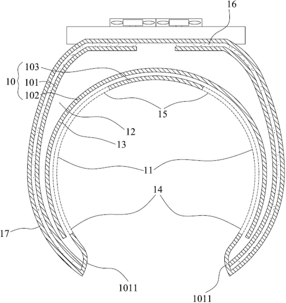
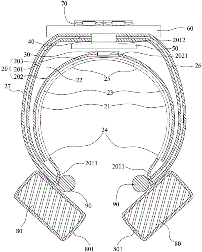
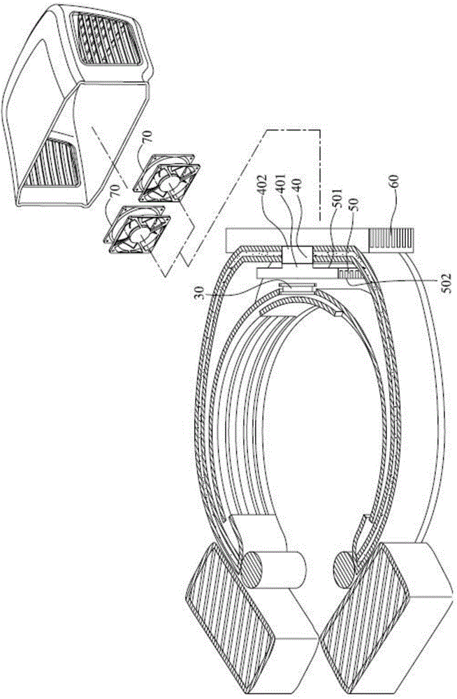
The invention discloses a gas backflow structure. The gas backflow structure comprises a shell and a flow guide element. The shell comprises a first side wall, a second side wall and a third side wall. The flow guide element is formed on the third side wall and toward the side edge of the outside. The first side wall extends from the two sides and form bending parts. The second side wall is formed between the first side wall and the third side wall. The third side wall is formed at the other end, oppositely toward the bending parts, of the flow guide element. A first air channel is formed between the first side wall and the second side wall. A second air channel is formed between the second side wall and the flow guide element, part of the bending parts as well as the third side wall and communicates with the first air channel, and a first air opening and a second air opening are formed in the junction of the flow guide element and the bending parts and the junction of the flow guide element and the third side wall correspondingly. Therefore, the temperature adjusting efficiency of an air conditioner device can be improved effectively.

Description

technical field [0001] The present invention relates to an air conditioner, and more specifically, relates to an air conditioner with an improved gas return structure. Background technique [0002] With the rapid development of science and technology, more and more home appliances are gradually trending toward miniaturization in design. Taking air conditioners as an example, traditional air conditioners are only suitable for closed and fixed spaces such as homes. On wearable devices, such as helmets, when a rider rides a bicycle in hot weather, cold air can be emitted from the helmet to maintain an appropriate temperature and achieve a cooling effect. [0003] However, such wearable air-conditioning devices have obvious disadvantages. First, limited by the existing structure of the helmet, the cold air discharged from the helmet can only be blown to a very limited area, and it is difficult to spread it evenly over a large area. emissions, making the cooling effect quite lim...

Claims


Application Information

Patent Timeline
IPC IPC(8): F24F13/08F24F5/00A42B1/24
Inventor 萧景中林宜养周育德
Owner MOAI ELECTRONICS
Why Eureka
Try Eureka