an in situ soil feeding 13 co 2 systems and methods
What is AI technical title?
AI technical title is built by Patsnap AI team. It summarizes the technical point description of the patent document.
A soil, in-situ technology, used in soil material testing, material inspection products, etc., to achieve the effect of reducing external interference and simple operation methods
Active Publication Date: 2018-01-23
BEIJING FORESTRY UNIVERSITY
View PDF5 Cites 0 Cited by
Summary
Abstract
Description
Claims
Application Information
AI Technical Summary
This helps you quickly interpret patents by identifying the three key elements:
Problems solved by technology
Method used
Benefits of technology
Problems solved by technology
In recent years, more and more studies have shown that atmospheric CO 2 It can enter the soil and be absorbed and fixed through the physical and chemical effects of the soil and the action of microorganisms. At present, this process is mostly determined by the method of stable isotope. However, the existing research mostly uses the method of indoor artificial simulation. 13 CO 2 The feeding test of in situ soil, due to the limitations of equipment and methods, has rarely been studied.
Method used
Image
Click on the blue label to locate the original text in one second.
Reading with bidirectional positioning of images and text.
Examples
Embodiment 1
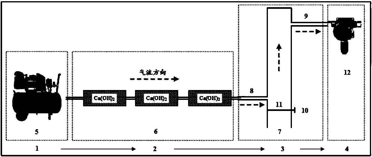
[0037] to combine figure 1 shown, one for feeding the soil 13 CO 2 system, including power unit 1, filter unit 2, feeding unit 3 and CO 2 detection device 4; wherein,
[0039] The filtering device includes a dryingpipe 6 and rubber conduits connected to the drying pipes; the drying pipes 6 are respectively connected through rubber conduits. In the drying tube 6 is solid Ca(OH) 2 ;
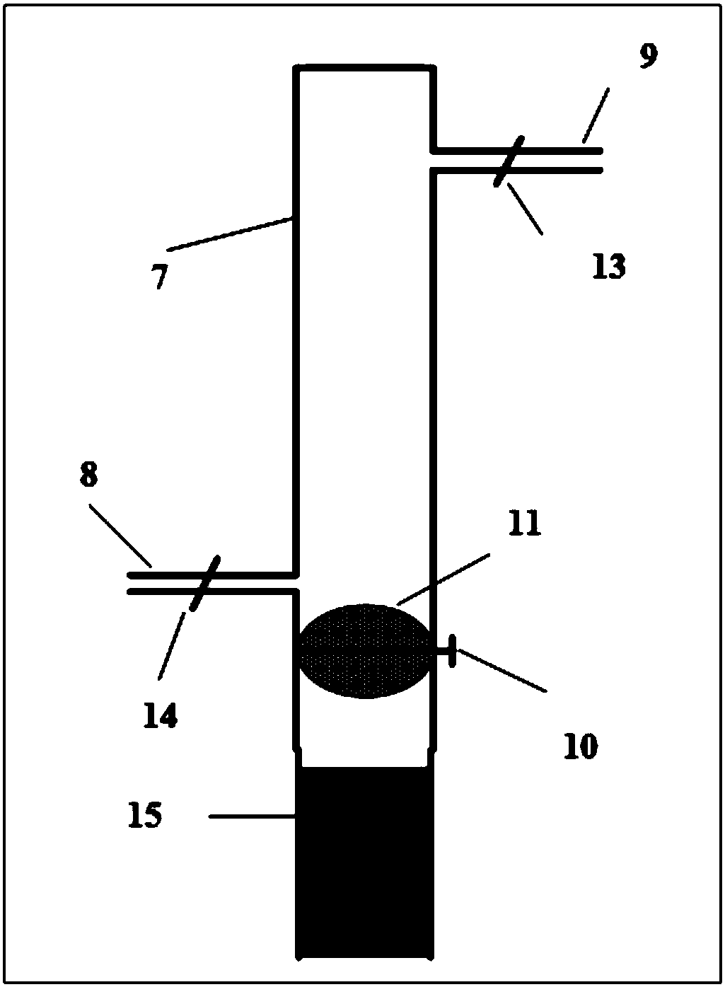
[0040] The feeding device comprises a plexiglass cylinder 7, an air injection pipe 8, an exhaust pipe 9, an exhaust pipe switch valve 13, an air injection pipe switch valve 14, a circular baffle 11, and a knob 10 for controlling the baffle switch;
[0041] The CO 2 The detection device is commercially available CO 2 analyzer12.
[0042] The air pump 5 provides power for gas flow for the whole system; the air pump 5 is connected with the filter device 2 .
[0043]In the filter device 2 of the present invention, the outsid...
Embodiment 2
[0049] Embodiment 2 feeding method
[0050] Feeding the soil using the system described in Example 1 13 CO 2 system feeding soil 13 CO 2 method, including the following steps:
[0051] 1) the soil ring 15 is driven into the ground vertically, and then the soil ring 15 is connected with the feeding device 3 ( figure 2 ), repeatedly wrap the joint with waterproof tape to prevent air leakage at the interface between the cylinder and the soil ring;
[0052] 2) The power unit 1, filter unit 2, feeding unit 3 and CO 2 The detection device 4 is connected; rotate the knob 10 on the cylinder to make the circular baffle 11 horizontal, so that the space above the glass cylinder baffle is in a completely sealed state;
[0053] 3) Open the switching valves 13, 14 of the gas injection pipe 14 and the exhaust pipe 13; start the air pump 5, control the air to 10Lmin -1 The flow rate flows out from the air pump 5, through Ca(OH) 2 The air in the drying pipe 6 enters the plexiglass cyl...
PUM
Abstract
The invention relates to the field of soil environmental research and testing and particularly discloses a system and method for feeding <13>CO2 to in-situ soil. The feeding system comprises a power unit used for providing airflow, a filter unit used for filtering out the CO2, a feeding unit and a CO2 testing unit; all the above-mentioned units are connected in sequence through a sealing pipeline thereamong; the body of the feeding unit is a container provided with an opening in the bottom, and an air injection pipe and an exhaust pipe which are communicated with the container are respectively arranged in the side wall of the container. By the system, feeding of the <13>CO2 to the in-situ soil can be performed under the condition that external interference is minimized, an existing method is improved and innovated, and the method feasible, accurate and convenient in operation is provided for the problem about research of whereabouts of the CO2 in atmosphere.
Description
technical field [0001] The invention relates to the field of soil environment research and detection, in particular to a method for feeding soil in situ 13 CO 2 systems and methods. Background technique [0002] Atmospheric CO 2 The issue of whereabouts has been controversial. In recent years, more and more studies have shown that atmospheric CO 2 It can enter the soil and be absorbed and fixed through the physical and chemical effects of soil and microbial action. At present, this process is mostly determined by the method of stable isotope, but the existing research is mostly carried out by indoor artificial simulation method 13 CO 2 Feeding experiments in situ soil and in situ soil feeding experiments are rarely studied because of the limitations of equipment and methods. [0003] Therefore, for a more in-depth and accurate study of CO 2 The process of where to go, there is an urgent need to develop a way to feed the soil in situ 13 CO 2 systems and methods. Co...
Claims
Application Information
Patent Timeline
Application Date:The date an application was filed.
Publication Date:The date a patent or application was officially published.
First Publication Date:The earliest publication date of a patent with the same application number.
Issue Date:Publication date of the patent grant document.
PCT Entry Date:The Entry date of PCT National Phase.
Estimated Expiry Date:The statutory expiry date of a patent right according to the Patent Law, and it is the longest term of protection that the patent right can achieve without the termination of the patent right due to other reasons(Term extension factor has been taken into account ).
Invalid Date:Actual expiry date is based on effective date or publication date of legal transaction data of invalid patent.

