
A design method for auxiliary sheds of DC voltage divider

A technology of DC voltage divider and design method, applied in voltage dividers, electrical components, insulators, etc., can solve problems affecting measurement accuracy, radial discharge, etc., to reduce the number of uses, reduce equipment costs, and ensure safe and stable operation. Effect

Active Publication Date: 2018-11-23
EXAMING & EXPERIMENTAL CENT OF ULTRAHIGH VOLTAGE POWER TRANSMISSION COMPANY CHINA SOUTHEN POWER GRID
View PDF6 Cites 0 Cited by
  • Summary
  • Abstract
  • Description
  • Claims
  • Application Information

AI Technical Summary

Problems solved by technology

Under adverse weather conditions such as rain, fog, dew, and snow, the radial potential difference exceeds the allowable value of the insulating material or insulating structure, which may easily cause radial discharge, thereby affecting the measurement accuracy

Method used


Image

  • A design method for auxiliary sheds of DC voltage divider
  • A design method for auxiliary sheds of DC voltage divider
  • A design method for auxiliary sheds of DC voltage divider

Examples


Embodiment Construction

[0025] The technical solutions in the embodiments of the present invention will be clearly and completely described below in conjunction with the drawings and embodiments. Apparently, the described embodiments are only some of the embodiments of the present invention, not all of them.

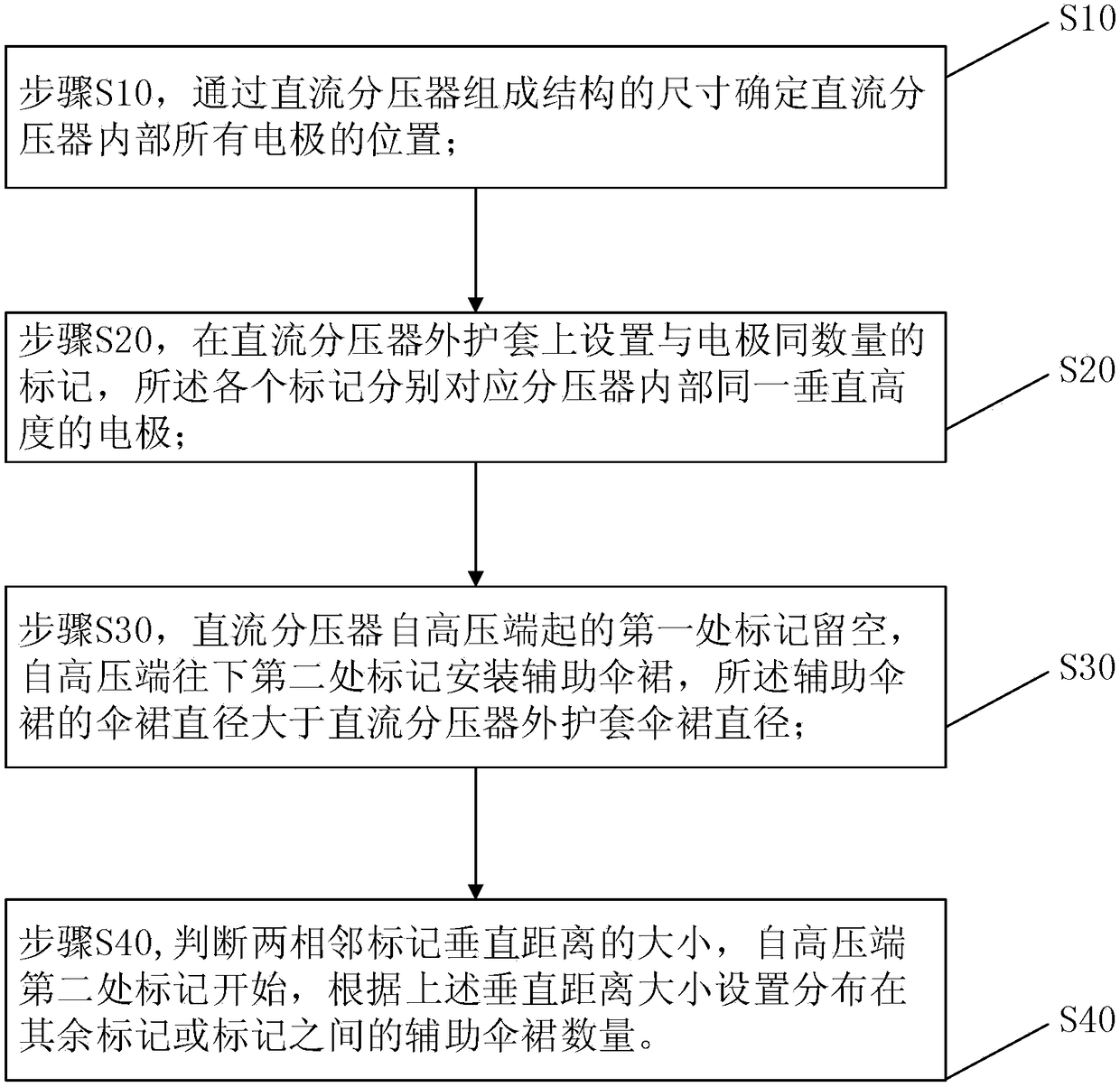
[0026] see figure 1 , is a flow chart of the steps of a method for designing a DC voltage divider auxiliary shed according to the present invention.

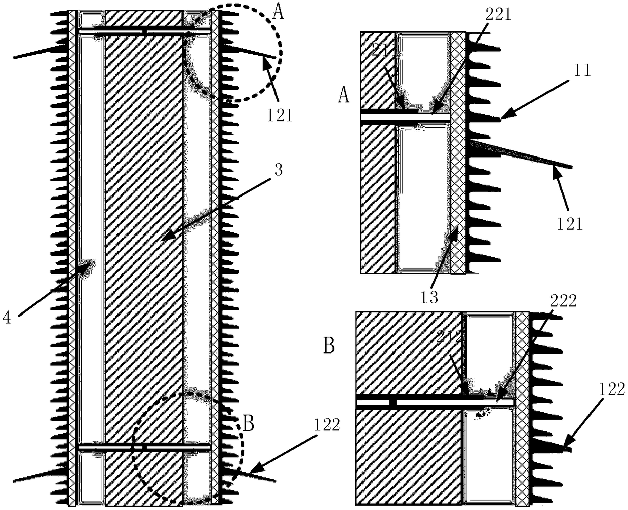
[0027] In the embodiment of the present invention, an auxiliary umbrella skirt is installed on the outer sheath 11 of the DC voltage divider, combined with figure 2 The structure schematic diagram of the DC voltage divider auxiliary shed and the enlarged schematic diagrams of parts A and B of the embodiment of the present invention. The DC voltage divider auxiliary shed design method includes the following steps:

[0028] Step S10, in order to determine the height of each electrode inside the DC voltage divider, determine the positions of all ...


PUM


Abstract

The invention discloses an auxiliary shed design method for a DC voltage divider, and the method comprises the following steps: S10, determining the position of each electrode in the DC voltage divider through the composition and structure size of the DC voltage divider; S20, setting marks on the bushing of the DC voltage divider, wherein the number of marks is equal to the number of electrodes, and each mark is corresponding to one electrode at the same vertical height in the voltage divider; S30, installing no auxiliary shed at the first mark of the DC voltage divider from a high-voltage end to the bottom, and installing an auxiliary shed at the second mark of the DC voltage divider from the high-voltage end to the bottom, wherein the width of each auxiliary shed is greater than the shed width of the bushing of the DC voltage divider; S40, judging the value of the vertical distance between two adjacent marks, starting at the second mark from the high-voltage end to the bottom, and setting the number of auxiliary sheds distributed at the remaining marks or between the marks according to the values of the vertical distances. The method provided by the invention achieves the prevention of rainstorm flashover of the DC voltage divider under the condition of rain, avoids the measurement abnormality of the DC voltage divider, and guarantees the safe and stable operation of a system.

Description

technical field [0001] The invention relates to the field of overhaul and maintenance of high-voltage primary equipment of a converter station / substation, in particular to a design method for an auxiliary shed of a DC voltage divider. Background technique [0002] Since 2010, there have been 5 rainstorm flashover accidents in the converter station equipment under the jurisdiction of China Southern Power Grid Corporation. The equipment that has rain flashover is mainly concentrated in the outdoor DC field, including DC voltage dividers, oil-immersed smoothing reactors, and outdoor 1.2 bushings. And isolating switch pillars, etc., the voltage level of rain flash equipment is mainly 500kV and 800kV. Among them, the rain flashover of DC voltage divider not only occurs in the South Grid area, but also occurs occasionally in the converter stations under the jurisdiction of the State Grid. In 2005 and 2009, rain flashover accidents occurred in the ±500kV Jiangling and Longquan conv...

Claims


Application Information

Patent Timeline
Patent Type & Authority Patents(China)
IPC IPC(8): G01R15/04H01B17/42
CPCG01R15/04H01B17/42
Inventor 韦晓星孙勇刘婉莹卢文浩陈伟楚金伟
Owner EXAMING & EXPERIMENTAL CENT OF ULTRAHIGH VOLTAGE POWER TRANSMISSION COMPANY CHINA SOUTHEN POWER GRID
Learn More