
Residual time difference correction method and device of azimuthal anisotropy

A azimuthal anisotropy and time difference correction technology, applied in measuring devices, instruments, scientific instruments, etc., can solve the problems of time-consuming and low accuracy of correction results.

Active Publication Date: 2016-12-07
BC P INC CHINA NAT PETROLEUM CORP +1
View PDF5 Cites 4 Cited by
  • Summary
  • Abstract
  • Description
  • Claims
  • Application Information

AI Technical Summary

Problems solved by technology

However, the reaction correction process takes a lot of time and the accuracy of the obtained azimuth anisotropy residual moveout correction results is not high

Method used


Image

  • Residual time difference correction method and device of azimuthal anisotropy
  • Residual time difference correction method and device of azimuthal anisotropy
  • Residual time difference correction method and device of azimuthal anisotropy

Examples


Embodiment Construction

[0038] In order to make the purpose, technical solutions, and advantages of the embodiments of the present application clearer, the embodiments of the present application will be further described in detail below in conjunction with the embodiments and the accompanying drawings. Here, the schematic embodiments and descriptions of the embodiments of the present application are used to explain the embodiments of the present application, but are not intended to limit the embodiments of the present application.

[0039] The specific implementation manners of the embodiments of the present application will be further described in detail below in conjunction with the accompanying drawings.

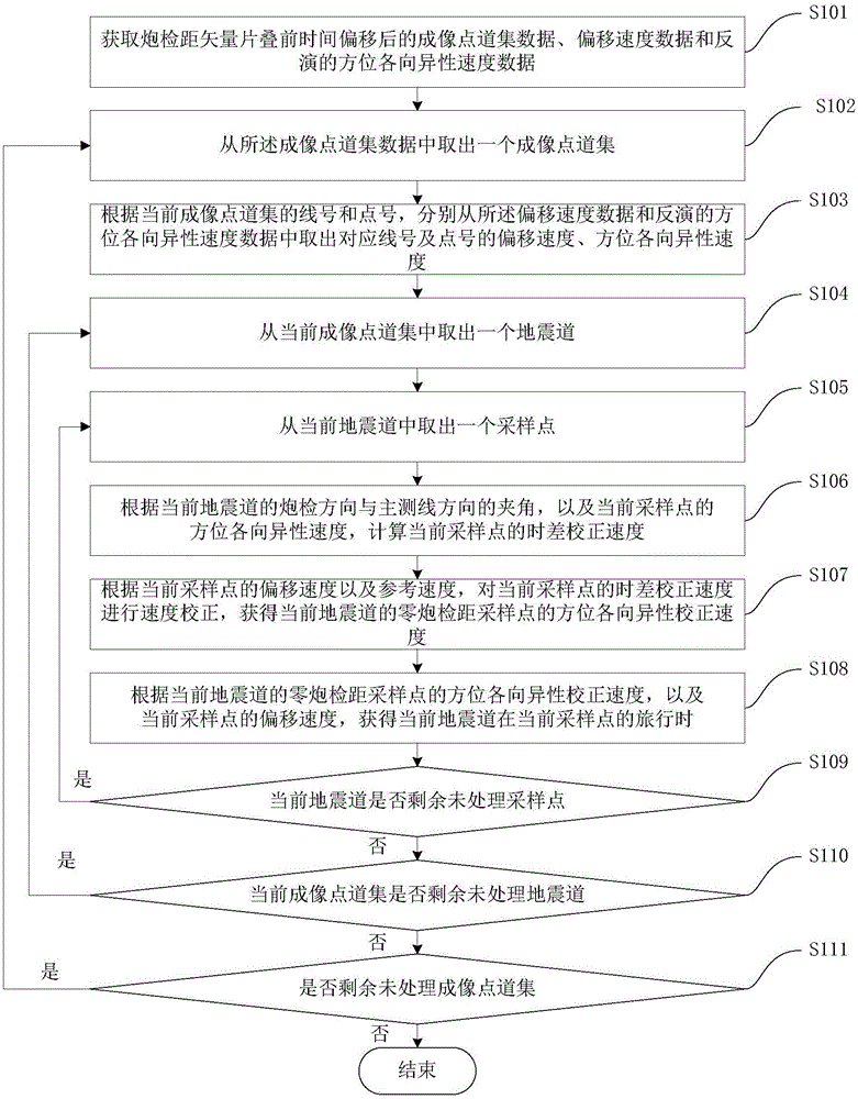
[0040] refer to figure 1 The azimuth anisotropic residual time difference correction method of the embodiment of the application shown includes the following steps:

[0041] Step S101 , acquiring imaging point gather data, migrated velocity data, and inverted azimuthal anisotropic velocity data...


PUM


Abstract

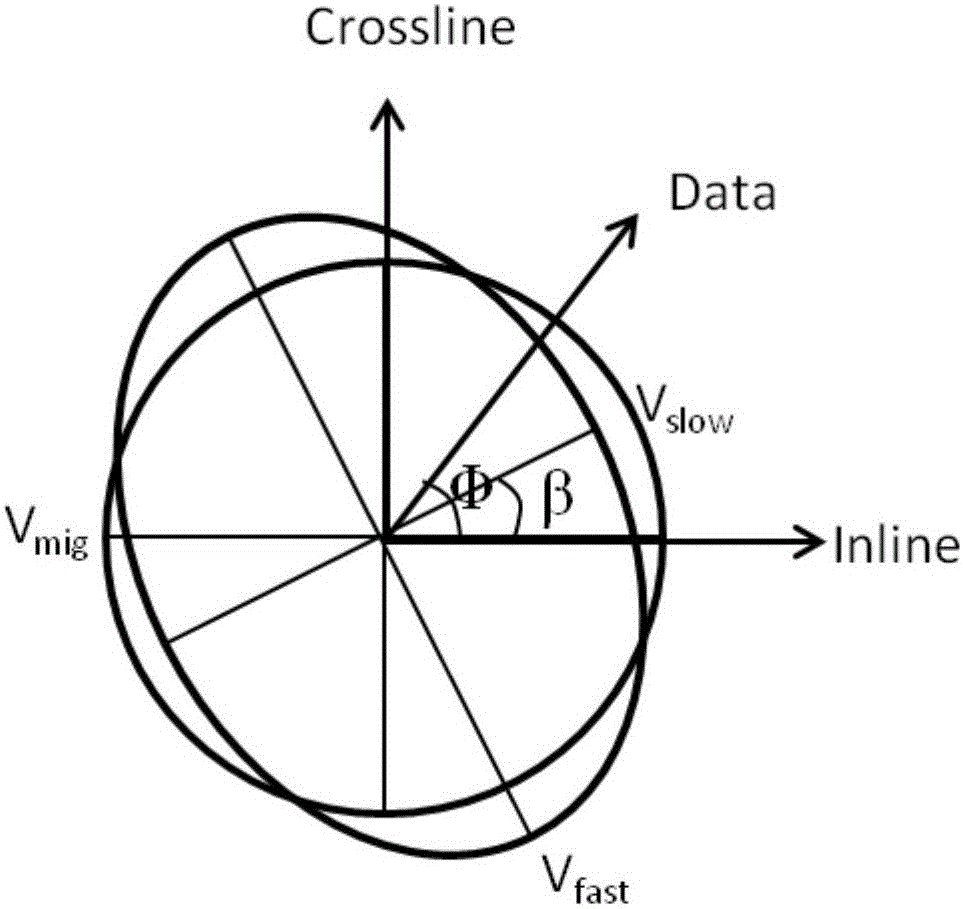
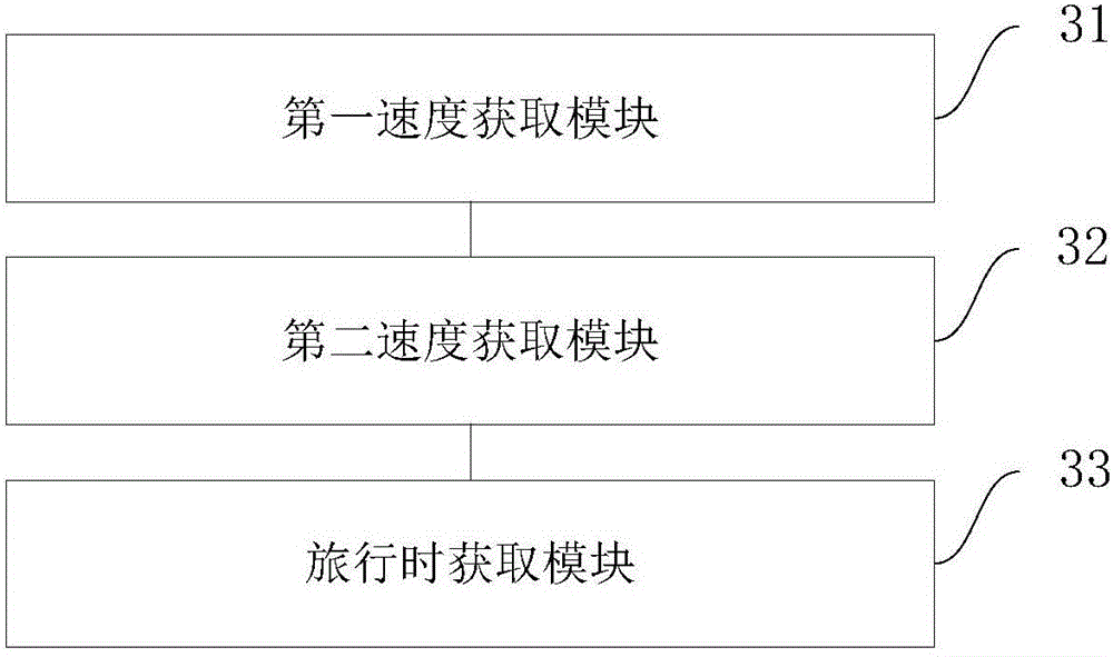
The invention provides a residual time difference correction method and device of azimuthal anisotropy. The method comprises that according to the included angle between a shot direction of a present seismic trace and the direction of a main measuring line as well as the azimuthally anisotropic speed of a present sampling point of the present seismic trace, a time difference correction speed of the present sampling point is calculated; according to the offset speed of the present sampling point and reference speed, the time difference correction speed of the present sampling point is corrected, and an azimuthally anisotropic correction speed of a zero-offset sampling point of the present seismic trace is obtained; and according to the azimuthally anisotropic correction speed of the zero-offset sampling point of the present seismic trace as well as the offset speed of the present sampling point, a sampling point value, when the present sampling point travels, of the present seismic trace at the position of travelling is obtained and serves as a result of residual time difference correction of azimuthal anisotropy. The processing efficiency and precision of residual time difference correction of azimuthal anisotropy are improved.

Description

technical field [0001] The present application relates to the technical field of wide-azimuth seismic data processing, in particular to an azimuth anisotropic residual moveout correction method and device. Background technique [0002] Oil and gas development and production practice and experience show that oil and gas reservoirs are often accompanied by fractures, which have an important impact on oil and gas migration, so the identification and analysis of fracture structures is an important research topic for oil and gas development. Wide-azimuth seismic exploration provides an important means for fracture detection. The obvious feature of fracture structure on wide-azimuth seismic data is the azimuthal anisotropy of seismic wave velocity, that is, the seismic wave propagation velocity changes with the change of observation azimuth. This feature will After migration imaging, the wide-azimuth seismic data imaging gather has inter-trace time difference, which leads to the d...

Claims


Application Information

Patent Timeline
IPC IPC(8): G01V1/36
CPCG01V1/362G01V2210/51G01V2210/586
Inventor 耿伟峰王文闯祝树云梁琰张秀丽周兴
Owner BC P INC CHINA NAT PETROLEUM CORP
Learn More