Imaging optical system

An imaging optical path and subsystem technology, applied in the field of projection display, can solve the problem that the imaging quality of the imaging optical path system cannot be adjusted, and achieve the effect of improving tolerance and realizing adjustment

Active Publication Date: 2019-03-12
QINGDAO HISENSE LASER DISPLAY CO LTD
View PDF7 Cites 0 Cited by
  • Summary
  • Abstract
  • Description
  • Claims
  • Application Information

AI Technical Summary

Problems solved by technology

[0006] In order to solve the technical problem that the imaging quality of the imaging optical path system in the prior art cannot be adjusted, the embodiment of the present invention provides an imaging optical path system, which improves the tolerance and debuggability, facilitates the adjustment of the imaging quality, thereby improving the overall imaging quality

Method used


Image

  • Imaging optical system
  • Imaging optical system
  • Imaging optical system

Examples


Embodiment Construction

[0041] In order to make the purpose, technical solution and advantages of the present invention clearer, the implementation of the present invention will be described in detail in a specific implementation below in conjunction with the accompanying drawings.

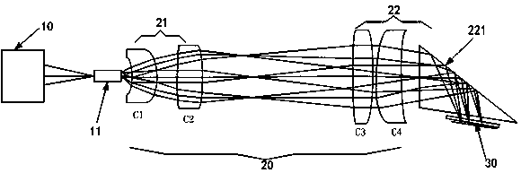
[0042] An embodiment of the present invention provides an imaging optical path system, such as figure 2 As shown, the imaging optical system may be a telecentric optical system. The imaging optical system includes:

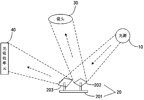
[0043] A light source 10 is used to provide an illumination light beam; specifically, the light source 10 may include a laser light source of at least one color, such as a blue laser light source and a fluorescent light source or an LED light source, or a blue laser light source, a red laser light source and a fluorescent light source or an LED A light source, or a three-color laser light source, in this implementation, the light source 10 provides sequential illumination beams of three primary colors.

...


PUM


Abstract

The invention discloses an imaging light path system and belongs to the field of projection display. The imaging light path system comprises a light source, an illuminating light path and a light valve, wherein the illuminating light path is a two-section type subsystem and comprises a front section subsystem and a rear section subsystem, the front section subsystem is used for receiving illumination beam provided by the light source to output first parallel light and converging the first parallel light beam on the object space focal plane of the rear section subsystem, the rear section subsystem is used for converting the converged light beam into second parallel light beam and making the second light beam enter the light incidence face of the light valve at a preset angle. The imaging light path system can improve the tolerance and debugging properties of the system and facilitates adjustment of imaging quality.

Description

technical field [0001] The invention relates to the field of projection display, in particular to an imaging optical path system. Background technique [0002] DLP (English: Digital Light Processing; abbreviation: DLP, digital optical processing) projector is a high-precision projector, including: light source, imaging optical system, digital micromirror device (English: Digital MicromirrorDevice; abbreviation: DMD) and lens Wait. Among them, the DMD is the core component of the DLP projector, including a control part, a rectangular substrate and a plurality of light valves (also called microlenses) arranged in an array on the substrate. The control part can control multiple Each light valve deflects in positive and negative directions. [0003] like figure 1 As shown, in the current DLP projector, the sequential three-primary color light provided by the light source 10 passes through the illumination optical path system ( figure 1 (not shown in the figure) is irradiated...

Claims


Application Information

Patent Timeline
Patent Type & Authority Patents(China)
IPC IPC(8): G03B21/20
CPCG03B21/206G03B21/2066G03B21/208
Inventor 李晓平
Owner QINGDAO HISENSE LASER DISPLAY CO LTD
Why Eureka
Try Eureka