Viscous debris flow river-blocking calculation method and application thereof

A calculation method and mud-rock flow technology, applied in calculation, special data processing applications, instruments, etc., can solve the problems of adverse mud-rock flow prevention and control effects, calculation errors, and the accuracy of mud-rock flow blocking rivers, etc., to simplify the judgment of factors and judgments of river blocking The effect of accurate model and concise judgment result

Active Publication Date: 2016-12-07
CHENGDU UNIVERSITY OF TECHNOLOGY
View PDF1 Cites 9 Cited by
  • Summary
  • Abstract
  • Description
  • Claims
  • Application Information

AI Technical Summary

Problems solved by technology

[0009] The debris flow Huijiang physical simulation test device disclosed in this patent document, although it can simulate the debris flow outbreak and the flow of the river, can study the influence of factors such as different solid sources, slope angles, river water flow rates, debris flow accumulation areas and river intersection angles on the debris flow of the Huijiang River. However, since the field data scale is much larger than the indoor test data, there are large errors in the actual calculation when the dimensions are not harmonious, which affects the accuracy of the judgment of debris flow blocking the river and is not conducive to improving the effectiveness of debris flow prevention and control.

Method used


Image

  • Viscous debris flow river-blocking calculation method and application thereof
  • Viscous debris flow river-blocking calculation method and application thereof
  • Viscous debris flow river-blocking calculation method and application thereof

Examples


Embodiment 1

[0049] A method for calculating river blocking by viscous debris flow, comprising the following steps:

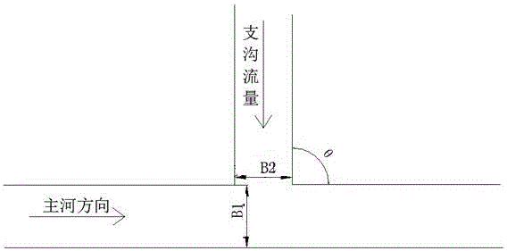
[0050] a. The confluence angle between the tributary ditch and the main river measured on the spot or on the topographic map , 85° 95°;

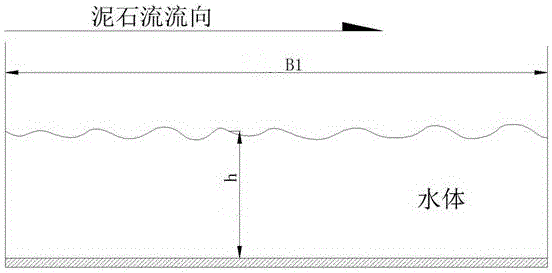
[0051] b. Measure the average width of the main river at the intersection of the main river and the tributaries B. 1 , unit m, main river flow Qm, unit m 3 / s, according to formula 1 to determine the single-width discharge Q of the main river 1 , unit m 2 / s;

[0052] (Formula 1);

[0053] c. Measure the average width of the tributary at the intersection of the main river and the tributary on the spot B 2 , unit m, debris flow flow , unit m 3 / s, according to the formula 2 to determine the flow rate of the single width of the tributary ditch 2 , unit m 2 / s;

[0054] (Formula 2);

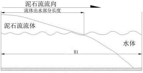
[0055] d. The single-width flow Q of the main river 1 and tributary single width flow 2 Substitute into Equation 3 to determine...

Embodiment 2

[0066] A method for calculating river blockage by viscous debris flow is characterized in that it comprises the following steps:

[0067] a. The confluence angle between the tributary ditch and the main river measured on the spot or on the topographic map , 85° 95°;

[0068] b. Measure the average width of the main river at the intersection of the main river and the tributaries B. 1 , unit m, main river flow Qm, unit m 3 / s, according to formula 1 to determine the single-width discharge Q of the main river 1 , unit m 2 / s;

[0069] (Formula 1);

[0070] c. Measure the average width of the tributary at the intersection of the main river and the tributary on the spot B 2 , unit m, debris flow flow , unit m 3 / s, according to the formula 2 to determine the flow rate of the single width of the tributary ditch 2 , unit m 2 / s;

[0071] (Formula 2);

[0072] d. The single-width flow Q of the main river 1 and tributary single width flow 2 Substitute in...

Embodiment 3

[0084] A method for calculating river blockage by viscous debris flow is characterized in that it comprises the following steps:

[0085] a. The confluence angle between the tributary ditch and the main river measured on the spot or on the topographic map , 85° 95°;

[0086] b. Measure the average width of the main river at the intersection of the main river and the tributaries B. 1 , unit m, main river flow Qm, unit m 3 / s, according to formula 1 to determine the single-width discharge Q of the main river 1 , unit m 2 / s;

[0087] (Formula 1);

[0088] c. Measure the average width of the tributary at the intersection of the main river and the tributary on the spot B 2 , unit m, debris flow flow , unit m 3 / s, according to the formula 2 to determine the flow rate of the single width of the tributary ditch 2 , unit m 2 / s;

[0089] (Formula 2);

[0090] d. The single-width flow Q of the main river 1 and tributary single width flow 2 Substitute into...


PUM


Abstract

The invention discloses a viscous debris flow river-blocking calculation method and an application thereof, belonging to the technical field of debris flow prevention and treatment engineering. The viscous debris flow river-blocking calculation method comprises the following steps of: obtaining a confluence angle of a branch channel and a main river as shown in the specification by measurement; measuring the average width B1 of the main river and the flow Qm of the main river at the confluence position of the main river and the branch channel, and determining the flow per unit width Q1 of the main river; measuring the average width B2 of the branch channel and the flow of the debris flow as shown in the specification at the confluence position of the main river and the branch channel, determining the flow per unit width of the branch channel as shown in the specification, determining the ratio of the flow per unit width of the branch channel and the main river as shown in the specification, measuring water depth h of the main river at the confluence position of the main river and the branch channel, determining a volume factor yt, measuring the yield stress of the debris flow as shown in the specification, and the density of the debris flow as shown in the specification, and determining a yield stress factor x of the debris flow; and judging whether river blocking can be caused by the viscous debris flow or not according to a judgment factor y. A debris flow river-blocking calculation model established in the invention has the characteristics of being harmonious in dimension and high in calculation result accuracy, and is capable of accurately judging viscous debris flow river-blocking; and thus, the debris flow prevention and treatment effect is improved.

Description

technical field [0001] The invention relates to the technical field of mud-rock flow prevention and control engineering, in particular to a calculation method for viscous mud-rock flow blocking rivers and its application. Background technique [0002] Debris flow refers to the landslides caused by heavy rain, snowstorm or other natural disasters in mountainous areas or other areas with deep valleys and steep terrain, carrying a large amount of sand and stones. Its area, volume, and flow are large, while landslides are small areas of diluted soil mountains. Typical debris flows are composed of viscous mud with coarse solid debris suspended and rich in silt and clay. Under appropriate terrain conditions, a large amount of water soaks the solid accumulations in the flowing water hillside or ditch bed, reducing its stability, and the solid accumulations saturated with water move under their own gravity, forming a debris flow. Debris flow is a disastrous geological phenomenon. ...

Claims


Application Information

Patent Timeline
Patent Type & Authority Applications(China)
IPC IPC(8): G06F17/50
CPCG06F30/367
Inventor 余斌杨晨源
Owner CHENGDU UNIVERSITY OF TECHNOLOGY
Why Eureka
Try Eureka