
Magnetic core of motor and manufacturing method of magnetic core

A manufacturing method and manufacturing method technology, applied in the direction of inductance/transformer/magnet manufacturing, magnetic core/yoke manufacturing, motor generator manufacturing, etc., which can solve the problems of large opening of the winding slot of the motor magnetic core and limitation of the length of the tooth crown.

Active Publication Date: 2016-12-07
JOHNSON ELECTRIC SHENZHEN
View PDF8 Cites 4 Cited by
  • Summary
  • Abstract
  • Description
  • Claims
  • Application Information

AI Technical Summary

Problems solved by technology

The disadvantage of this solution is that the length of the tooth crown is limited, resulting in too large opening of the winding slot of the motor core

Method used


Image

  • Magnetic core of motor and manufacturing method of magnetic core
  • Magnetic core of motor and manufacturing method of magnetic core
  • Magnetic core of motor and manufacturing method of magnetic core

Examples


Embodiment Construction

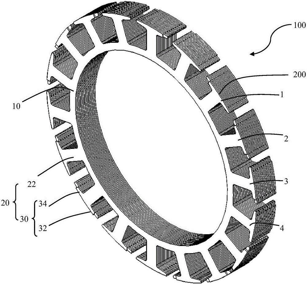
[0056] refer to figure 1 and figure 2 , an embodiment of the present invention provides a motor core 100, including an annular yoke 10, a tooth 20 protruding from the yoke 10, and a tooth extending circumferentially from the end of the tooth body 22 of the tooth 20. Crown 30. The tooth crown 30 of each tooth portion 20 includes a left half tooth crown 32 and a right half tooth crown 34, and the dimensions of the left half tooth crown 32 and the right half tooth crown 34 along the circumferential direction of the yoke 10 are respectively referred to as the left half tooth crown. length, the length of the right half crown. The motor magnetic core 100 is composed of several layers of chips 200 (see figure 2 ) superimposed. The motor magnetic core 100 is made of magnetically permeable material, preferably an iron core.

[0057] refer to figure 2 and image 3 , figure 2 The first layer of chips is formed by cutting off the second half of the last tooth set on the basis ...


PUM


Abstract

The invention provides a magnetic core of a motor and a manufacturing method of the magnetic core. The magnetic core of the motor comprises a yoke part, teeth extending outwards from the yoke part and tooth crowns extending from the tail ends of the teeth along the circumferential direction, wherein each tooth crown comprises a left half tooth crown and a right half tooth crown; the magnetic core of the motor is formed by stacking multiple layers of first chips and multiple layers of second chips; each layer of chip comprises multiple groups of first-class teeth, second-class teeth, third-class teeth and forth-class teeth which are sequentially arranged; the left half tooth crowns of the first-class teeth are short tooth crowns and the right half tooth crowns are long tooth crowns; the left half tooth crowns and the right half tooth crowns of the second-class teeth are the short tooth crowns; the left half tooth crowns of the third-class teeth are the long tooth crowns and the right half tooth crowns are the short tooth crowns; the left half tooth crowns and the right half tooth crowns of the fourth-class teeth are the long tooth crowns; and the first-class teeth, the second-class teeth, the third-class teeth and the fourth-class teeth of the first chips are overlapped with the third-class teeth, the fourth-class teeth, the first-class teeth and the second-class teeth of the second chip respectively. By implementation of the magnetic core of the motor, the notch width can be reduced and the cogging torque can be reduced. By the manufacturing method provided by the invention, the material can be saved and the cost can be reduced.

Description

【Technical field】 [0001] The invention relates to the field of motors, and more specifically, to a motor magnetic core and a manufacturing method thereof. 【Background technique】 [0002] A conventional motor magnetic core includes an annular yoke and a plurality of teeth protruding outward from the yoke, each tooth has a tooth crown at the end, and each tooth crown includes a left half crown and a right half crown. Generally, the dimension of the left half crown along the circumferential direction of the yoke is called the length of the left half crown, and the dimension of the right half crown along the circumferential direction of the yoke is called the length of the right half crown. [0003] The above-mentioned motor magnetic core is formed by stacking several layers of ring-shaped chips. If the ring-shaped chip is punched out directly from the sheet, a large amount of waste material will be generated, resulting in waste of material. [0004] An improved solution is t...

Claims


Application Information

Patent Timeline
Patent Type & Authority Applications(China)
IPC IPC(8): H02K1/14H02K1/24H02K1/16H02K1/26H02K15/02
CPCH02K1/14H02K1/16H02K1/24H02K1/26H02K15/022H02K15/026H01F3/02H01F41/0233
Inventor 李越姜茂雄赵健王勇李勇廖燕飞叶迎松华海军
Owner JOHNSON ELECTRIC SHENZHEN
Learn More