
Built-in permanent-magnet synchronous motor

A permanent magnet synchronous motor, built-in technology, applied in the direction of magnetic circuits, electric components, electrical components, etc., can solve the problems of weakening the motor, increasing costs, and requiring high torque fluctuation standards

Inactive Publication Date: 2016-12-07
GUANGDONG UNIV OF TECH
View PDF5 Cites 5 Cited by
  • Summary
  • Abstract
  • Description
  • Claims
  • Application Information

AI Technical Summary

Problems solved by technology

[0002] We know that permanent magnet synchronous motors have a series of advantages such as simple structure, low loss, high power factor, and high efficiency; however, permanent magnet synchronous motors have some defects, such as torque fluctuations, which will affect the control accuracy of the system and cause vibration and noise. Places with high requirements for working performance have higher requirements for torque fluctuation standards
[0003] In order to weaken the torque fluctuation of the motor, in terms of the design of the motor body, the existing surface-mounted permanent magnet motor rotors generally use unequal-thickness magnets, or split oblique poles or inclined slots; and for built-in rotor structures, generally use The way of the chute, the chute makes the manufacturing complicated and increases the cost, and at the same time may reduce the output electromagnetic torque

Method used


Image

  • Built-in permanent-magnet synchronous motor
  • Built-in permanent-magnet synchronous motor
  • Built-in permanent-magnet synchronous motor

Examples


Embodiment Construction

[0019] The following will clearly and completely describe the technical solutions in the embodiments of the present invention with reference to the accompanying drawings in the embodiments of the present invention. Obviously, the described embodiments are only some, not all, embodiments of the present invention. Based on the embodiments of the present invention, all other embodiments obtained by persons of ordinary skill in the art without making creative efforts belong to the protection scope of the present invention.

[0020] In order to enable those skilled in the art to better understand the solution of the present invention, the present invention will be further described in detail below in conjunction with the accompanying drawings and specific embodiments.

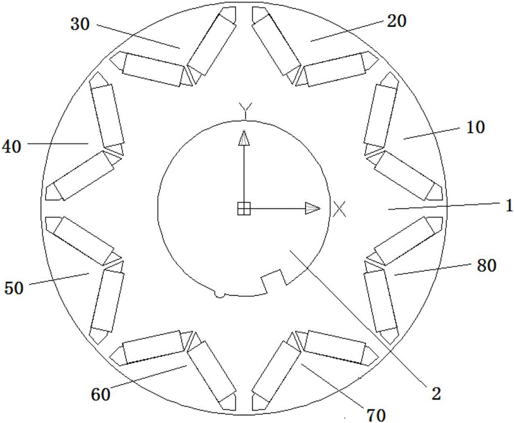
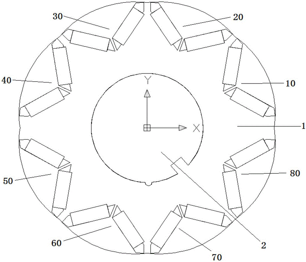
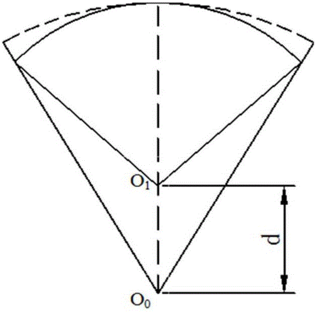
[0021] Please refer to Figure 1 to Figure 5 , figure 1 Schematic diagram of the structure of the interior permanent magnet synchronous motor before the magnetic pole offset provided by the embodiment of the presen...


PUM


Abstract

The invention discloses a built-in permanent-magnet synchronous motor. The built-in permanent-magnet synchronous motor comprises a rotor iron core and a rotor shaft, wherein a plurality of pairs of magnetic poles are arranged on the rotor iron core and are arranged around the rotor shaft, the plurality of pairs of magnetic poles are divided to two groups of magnetic poles in average, and for arbitrary one group of magnetic poles, each magnetic pole is arranged at the other side, facing a symmetric middle line in a deviation way by taking the symmetric middle line arranged between the magnetic poles at two sides of the group as an axis, and the distances between magnetic isolation bridges between the magnetic poles in the arbitrary one group of magnetic poles are equal. In the abovementioned built-in permanent-magnet synchronous motor, a mode of magnetic pole deviation is relatively simple, the rotor structure of the built-in permanent-magnet synchronous motor is relatively convenient to improve, and the built-in permanent-magnet synchronous motor is also easy to operate; and moreover, with the built-in permanent-magnet synchronous motor improved according to the abovementioned mode, the cogging torque amplitude can be reduced to a great extent, and the fluctuation of an output torque is greatly reduced.

Description

technical field [0001] The invention relates to the technical field of permanent magnet motors, in particular to a built-in permanent magnet synchronous motor. Background technique [0002] We know that permanent magnet synchronous motors have a series of advantages such as simple structure, low loss, high power factor, and high efficiency; however, permanent magnet synchronous motors have some defects, such as torque fluctuations, which will affect the control accuracy of the system and cause vibration and noise. Places with high requirements for work performance have higher requirements for torque fluctuation standards. [0003] In order to weaken the torque fluctuation of the motor, in terms of the design of the motor body, the existing surface-mounted permanent magnet motor rotors generally use unequal-thickness magnets, or split oblique poles or inclined slots; and for built-in rotor structures, generally use In the way of the chute, the chute complicates the manufactu...

Claims


Application Information

Patent Timeline
Patent Type & Authority Applications(China)
IPC IPC(8): H02K1/27H02K29/03
CPCH02K1/2766H02K29/03
Inventor 方超黄开胜朱兴旺吴帮超黄光建
Owner GUANGDONG UNIV OF TECH
Learn More