
High speed stabilizing drive control method of satellite-borne large inertia load mechanism

A large inertia load, star-loaded technology, applied in the direction of vector control system, motor generator control, AC motor control, etc., can solve the problems of large instantaneous energy storage of motors, torque fluctuations, response time and overshoot difficult to adjust , to achieve the effect of improving utilization rate, reducing current harmonic component, and reducing torque ripple

Active Publication Date: 2015-05-27
XIAN INSTITUE OF SPACE RADIO TECH
View PDF3 Cites 0 Cited by
  • Summary
  • Abstract
  • Description
  • Claims
  • Application Information

AI Technical Summary

Problems solved by technology

[0006] The greater the moment of inertia of the load, the greater the mechanical time constant of the motor control system, it is difficult to reconcile the response time and overshoot of the system, and it is difficult to guarantee the control dynamic characteristics of the motor when the speed changes; and there are disturbances in the inertial system Factors such as the cogging torque fluctuation of the motor, the quantization error of the measurement sensor, and the dead zone of the inverter, etc., these non-linear factors will generate torque fluctuations in the system, thereby causing speed fluctuations
[0007] When the load with such a large inertia rotates, the torque will generate a large inertia torque. The instantaneous energy storage of the motor is large, and the fluctuation of its speed will inevitably have a great impact on the attitude of the whole star, which will cause damage to other objects on the star. Pointing accuracy requires that the pointing of the load instrument causes interference; if the velocity fluctuates greatly, it may even affect the life of the entire star

Method used

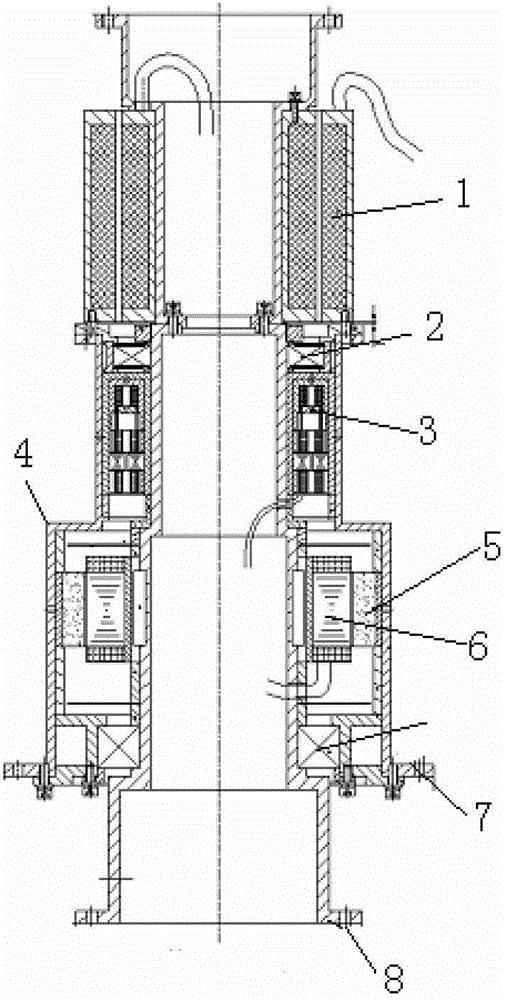
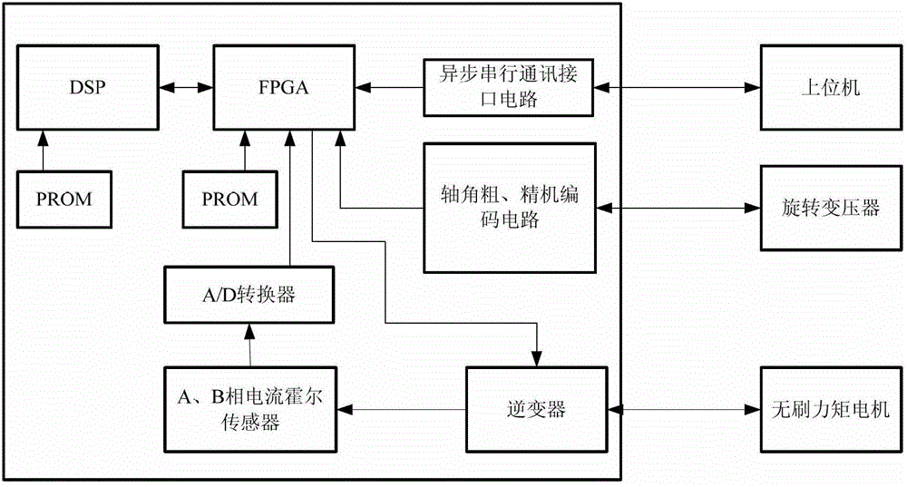
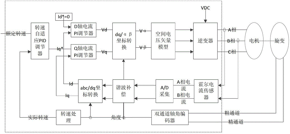

Image

  • High speed stabilizing drive control method of satellite-borne large inertia load mechanism
  • High speed stabilizing drive control method of satellite-borne large inertia load mechanism
  • High speed stabilizing drive control method of satellite-borne large inertia load mechanism

Examples


Embodiment Construction

[0050] In order to better understand the present invention, the coordinate system involved in the present invention will be described first.

[0051] Two-phase stator coordinate system (αβ coordinate system):

[0052] Two-phase symmetrical windings, passing two-phase symmetrical currents, also generate a rotating magnetic field. For a vector, it is customary to use a two-phase Cartesian coordinate system to describe it mathematically, so a two-phase coordinate system (αβ coordinate system) is defined.

[0053] The two-phase fixed windings α and β of the motor are 90 degrees apart in space, and the two-phase balanced AC current i α ,i β 90 degrees out of phase.

[0054] Three-phase stator coordinate system (abc coordinate system):

[0055] The three-phase stator windings of the permanent magnet synchronous motor have a mutual difference of 120 degrees in space, and are defined as a, b, and c axes along their axes, forming an abc coordinate system.

[0056] Rotor coordinate ...


PUM


Abstract

A high speed stabilizing drive control method of a satellite-borne large inertia load mechanism includes the following steps: (1) powering direct currents on a motor and calculating the phase difference of the motor and a rotary transformer after the load mechanism is stabilized; (2) collecting the current rotating speed of the motor at the current speed ring sampling instant and calculating torque electric currents; (3) collecting the electric currents iA and the electric currents iB of the motor at the current speed ring sampling instant to obtain the harmonic frequency spectrum, the amplitude and the phase of the iA and the iB; (4) conducting harmonic compensation on the iA and the iB; (5) converting the A-phase winding currents and the B-phase winding currents of the motor after compensation under a rotor coordinate system; (6) calculating the two-shaft voltage of the rotor coordinate system; (7) determining the three-phase time value of a PWM waveform generator, wherein a SVPWM waveform generator generates voltage waves according to the three-phase time value, and the voltage waves are loaded on a motor winding to control the motor; (8) entering the next current ring sampling instant, and switching to the step (3) to execute repeatedly; (9) entering the next current ring sampling instant, and switching to the step (2) to execute repeatedly.

Description

technical field [0001] The method relates to a control driving method for a rotating mechanism with large inertia, and especially requires high speed stability precision, and belongs to the technical field of antenna control. Background technique [0002] The scanning mechanism of the microwave radiometer and the scanning mechanism of the scatterometer are respectively used to drive the radiometer and the scatterometer to perform conical scanning on the ground, and carry the structure of the micro-detection head and internal electronic equipment to realize the observation of the ground. The mass of the rotating part of the scatterometer is 76.2kg, and the moment of inertia of the radiometer is 7.8kgm 2 (the mass of the rotating part is 61.3kg), and rotate at a constant speed of 95° / s respectively. [0003] The scanning mechanism, also known as the load mechanism, adopts the same direct drive method to realize the rigid coupling between the motor and the load to improve the ...

Claims


Application Information

Patent Timeline
Patent Type & Authority Patents(China)
IPC IPC(8): H02P21/14H02P27/12H02P21/22
Inventor 周勇乔璐马超张恒超闫剑虹
Owner XIAN INSTITUE OF SPACE RADIO TECH
Learn More