Downlink precoding method for multi-user distributed MIMO multi-antenna system

A multi-antenna system and downlink technology, applied in the field of multi-user distributed MIMO multi-antenna system downlink precoding, can solve the problems of joint processing of unreceived signals, mutual interference of received signals, etc.

Active Publication Date: 2016-12-07
SOUTHEAST UNIV
View PDF14 Cites 4 Cited by
  • Summary
  • Abstract
  • Description
  • Claims
  • Application Information

AI Technical Summary

Problems solved by technology

In the downlink of a distributed MIMO multi-antenna system, RAUs distributed everywhere can transmit data for multiple users in the same time-frequency resource. Since users located in d

Method used


Image

  • Downlink precoding method for multi-user distributed MIMO multi-antenna system
  • Downlink precoding method for multi-user distributed MIMO multi-antenna system
  • Downlink precoding method for multi-user distributed MIMO multi-antenna system

Examples


Embodiment 1

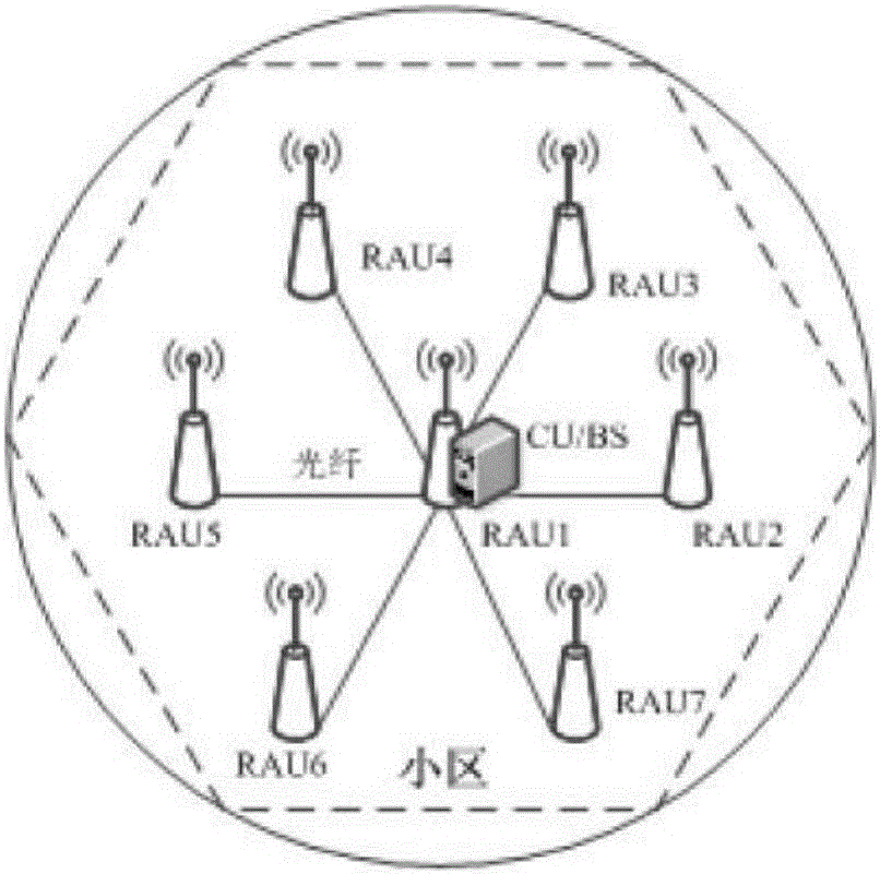
[0097] Embodiment 1 A Distributed MIMO Multi-antenna System Scenario

[0098] For the distributed MIMO multi-antenna system, the cell radius is set to 1km, and the system bandwidth is in Hz. like image 3 As shown, it is assumed that there are 7 RAUs in the cell, and each RAU is equipped with 4 antennas. One of the RAUs is located in the center of the cell, and the remaining 6 RAUs are evenly distributed on a circle with a radius of R / 2 at an angle of 60°. Each RAU passes through Optical fiber is connected to CU / BS. For BD precoding and the precoding proposed in the present invention, the receiving end adopts the maximum SINR to carry out receiving combination design. Since BD precoding requires that the total number of transmitting antennas is not less than the total number of receiving antennas, the actual total number of transmitting antennas is selected to be equal to the total number of receiving antennas. The number of receiving antennas. The number of transmitting an...

Embodiment 2

[0099] Embodiment 2 A centralized MIMO multi-antenna system scenario

[0100] As a comparison, the average data rate and average symbol error rate performance of the precoding joint optimization method proposed in the present invention in a centralized MIMO multi-antenna system (C-MIMO) are also given by simulation. For a centralized MIMO multi-antenna system, the radius of the cell is set to 1 km, the system bandwidth is in Hz, there is a base station in the cell, located in the center of the cell, and the number of antennas of the base station is equal to that of all RAUs in the distributed MIMO multi-antenna system (D-MIMO) The sum of the number of antennas is 28, and 16 antennas are selected from the base station antennas to transmit data for the user. In a centralized MIMO multi-antenna system, the system average data rate and average symbol error rate of the joint optimization method based on SLNR precoding, the joint optimization method based on weighted SLNR precoding,...

Embodiment 3

[0101] Embodiment 3 A scenario where the number of transmit antennas changes in a distributed MIMO multi-antenna system

[0102] Same as the distributed MIMO multi-antenna system in Embodiment 1, the cell radius is set to 1km, the system bandwidth is in Hz, there are 7 RAUs in the cell, each RAU is equipped with 4 antennas, one RAU is located in the center of the cell, and the remaining 6 Each RAU is evenly distributed on a circle with a radius of R / 2 at an angle of 60°. Each RAU is connected to the CU / BS through an optical fiber. The transmission signal-to-noise ratio is 20dB. The principle of minimum path loss selects the required number of transmit antennas from the antennas of all RAUs. Variation curves of the system average data rate with the number of transmitting antennas for the joint optimization method based on SLNR precoding, the joint optimization method based on weighted SLNR precoding, the iterative joint optimization method based on weighted SLNR precoding, and ...


PUM


Abstract

The invention discloses a downlink precoding method for a multi-user distributed MIMO (Multiple Input Multiple Output) multi-antenna system. The method comprises the following steps of S1: deploying M remote antenna units in a community, wherein each remote antenna unit is connected to a central processing unit through an optical fiber, each remote antenna unit is configured with Nm transmitting antennae, m equals 1, 2, ..., M, K active users exist, each user is configured with Lk receiving antennae, and k equals 1, 2, ..., K; S2: adopting a coordinated multi-point transmission method in the community for the system, combining the remote antenna units for sending data to the users, and selecting the required remote antenna unit from all the remote antenna units according to an average path loss minimum principle by using a selective transmission policy to send the data to the users; and S3: adopting a signal-to-interference and noise ratio criterion-based receiving combination method for receiving the data at a receiving end.

Description

technical field [0001] The invention relates to a wireless and mobile communication system, in particular to a downlink precoding method of a multi-user distributed MIMO multi-antenna system. Background technique [0002] Multiple Input Multiple Output (MIMO, Multiple Input Multiple Output) multi-antenna is one of the research focuses of LTE-Advanced and next-generation mobile communication (5G). It can make full use of space resources and realize multiple transmission and multiple reception through multiple antennas. When spectrum resources and antenna transmission power are increased, the system channel capacity can be doubled. Future wireless communication systems need to provide high data rate services. Distributed antennas are regarded as an effective method to shorten the wireless transmission distance between transceivers and support high data rates. It has become an important candidate for future mobile communications. Distributed antennas Based on CoMP has been ado...

Claims


Application Information

Patent Timeline
IPC IPC(8): H04B7/04H04B7/08
CPCH04B7/0452H04B7/0456H04B7/0857
Inventor 王向阳万望桃杨静雯
Owner SOUTHEAST UNIV
Why Eureka
Try Eureka