Lock hole drilling machine for clothes

A technology of punching machine and buttonhole, which is applied in the direction of sewing tools and other directions, can solve the problems of inconvenient operation and low buttonhole efficiency, and achieve the effect of convenient operation, high buttonhole efficiency and good buttonhole quality.

Inactive Publication Date: 2016-12-14
陆峰
2 Cites 0 Cited by

AI-Extracted Technical Summary

Problems solved by technology

[0003] The purpose of the present invention is to provide a keyhole punching machine for clothing, which ...

Abstract

The invention relates to the technical field of mechanical devices, in particular to a lock hole drilling machine for clothes. The lock hole drilling machine comprises a base and further comprises a lifting support, a beam, a positioning part, an operation part and a clamping part which are arranged at the upper end of the base. The lifting support comprises a stand column, a connecting ring cavity, a stand, a steering part, a steering handle, a slide rod, a main supporting body, a rotating head and a lateral side baffle. The lock hole drilling machine is convenient to operate, convenient to adjust, high in lock hole drilling efficiency and good in lock hole quality.

Application Domain

Clothes making applicances

Technology Topic

Mechanical devicesEngineering +1

Image

  • Lock hole drilling machine for clothes
  • Lock hole drilling machine for clothes
  • Lock hole drilling machine for clothes

Examples

  • Experimental program(1)

Example Embodiment

[0014] In order to make it easy to understand the technical means, creative features, goals and effects achieved by the present invention, the present invention will be further explained below in conjunction with the drawings and specific embodiments.
[0015] Combine Figure 1 to Figure 3 The buttonhole punching machine for clothing of the present invention will be described in detail.
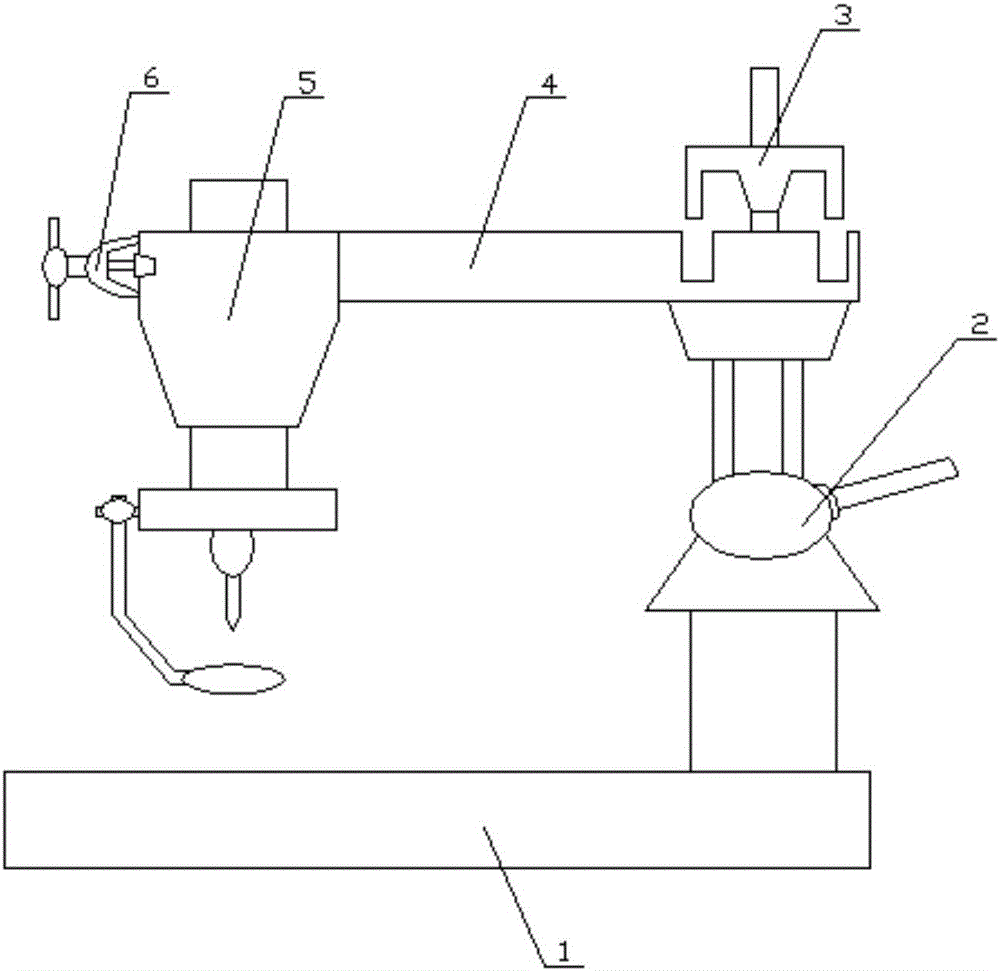
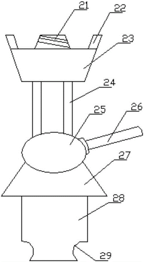
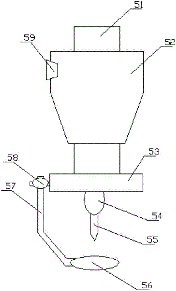
[0016] The buttonhole punching machine for clothing of the present invention includes a base 1, and further includes a lifting bracket 2 provided at the upper end of the base 1, a cross beam 4 provided at the upper end of the lifting bracket 2, and The positioning member 3 at the upper end of the beam 4, the operating member 5 provided at the end of the beam 4, and the clamping member 6 provided on the side wall of the operating member 5; the lifting bracket 2 includes a column 28 A connecting ring cavity 29 recessed in the side wall of the upright column 28 along the radial direction of the upright column 28, a base 27 arranged at the upper end of the upright column 28, and screwed on the upper part of the base 27 The steering member 25, the steering handle 26 that penetrates the steering member 25 along the radial direction of the steering member 25, the slide rod 24 that penetrates the upper part of the steering member 25, and the slide rod 24 is provided on the slide rod. The main support 23 at the upper end of the main support 23, the rotary joint 21 and the side baffle 22 provided at the upper end of the main support 23; the rotary joint 21 is provided at the center of the main support 23, and the side The side baffle 22 is arranged at the edge of the main support body 23.
[0017] The main support body 23 is in the shape of a truncated cone; the rotary joint 21 is in the shape of a truncated cone, and a first connecting thread is spirally recessed in the side wall of the rotary joint 21; the rotary joint 21 and the main support body 23 coaxial; along the axial direction of the main support body 23, a sliding hole is pierced in the main support body 23, the sliding hole and the sliding rod 24 are adapted; the number of the sliding rod 24 The steering member 25 is ellipsoidal; along the radial direction of the steering member 25 in the steering member 25 is penetrated with a first rotating hole, the first rotating hole and the steering handle 26 Adaptation; A first rotating groove is recessed in the upper part of the base 27, and the first rotating groove is adapted to the steering member 25.
[0018] The operating member 5 includes a main operating member 52, a guide member 51 penetrating through the main operating member 52, a side connector 59 embedded in the side wall of the main operating member 52, and screwing on the main operating member 52. The operation dial 53 at the lower end of the guide member 51, the main needle holder 54 screwed on the lower side of the operation dial 53, the needle 55 threaded through the main needle holder 54, and the operation dial 53 The rotation adjustment member 58 on the side wall of the side wall, the side rod 57 passing through the rotation adjustment member 58 and the pressing member 56 provided at the lower end of the side rod 57.
[0019] The guide member 51 is cylindrical; the operation panel 53 is disc-shaped; the upper part of the operation panel 53 is recessed with a first fixing groove, and the first fixing groove is adapted to the guide member 51; The outer wall of the main needle holder 54 is an ellipsoidal surface; a first needle hole is penetrated in the main needle holder 54 along the radial direction of the main needle holder 54, and the first needle hole and the needle 55 Along the radial direction of the operating plate 53, a first adjusting cavity is penetrated into the operating plate 53, and the first adjusting cavity is adapted to the rotation adjusting member 58; the side rod 57 includes The vertical portion and the inclined portion; the pressing member 56 is oval; the pressing member 56 is recessed with a first clamping groove, and a first clamping buckle is provided at the lower part of the inclined portion, so The first clamping buckle is compatible with the first clamping groove; the pressing member 56 is located directly below the needle 55.
[0020] The positioning component 3 includes a main locking body and a lifting adjustment rod passing through the main locking body; a locking groove is recessed on the upper part of the beam 4, and the locking groove is compatible with the main locking body.
[0021] The above shows and describes the basic principles, main features and advantages of the present invention. Those skilled in the industry should understand that the present invention is not limited by the above-mentioned embodiments. The above-mentioned embodiments and the description only illustrate the principles of the present invention. The present invention will have various aspects without departing from the spirit and scope of the present invention. Various changes and improvements, these changes and improvements fall within the scope of the claimed invention. The scope of protection claimed by the present invention is defined by the appended claims and their equivalents.

PUM

no PUM

Description & Claims & Application Information

We can also present the details of the Description, Claims and Application information to help users get a comprehensive understanding of the technical details of the patent, such as background art, summary of invention, brief description of drawings, description of embodiments, and other original content. On the other hand, users can also determine the specific scope of protection of the technology through the list of claims; as well as understand the changes in the life cycle of the technology with the presentation of the patent timeline. Login to view more.

Similar technology patents

Graphene film and preparation method therefor

Owner:CHANGZHOU FUXI TECH CO LTD

Driving working load calculation method of automobile driver

InactiveCN101690666AImprove accuracy and timelinessEasy to operate
Owner:BEIJING UNIV OF TECH

Classification and recommendation of technical efficacy words

  • Easy to adjust
  • easy to operate

High-isolation double-unit MIMO (multiple input multiple output) antenna array

InactiveCN102832452AEasy to adjustgood impedance characteristics
Owner:GUILIN UNIV OF ELECTRONIC TECH

Method for regulating high power laser apparatus light path alignment

InactiveCN101266340Asimple equipmentEasy to adjust
Owner:SHANGHAI INST OF OPTICS & FINE MECHANICS CHINESE ACAD OF SCI

Conductive rubber and application thereof

ActiveCN102176341AGood for dust resistanceEasy to adjust
Owner:DONGGUAN MEMTECH ELECTRONICS MEMTECH ELECTRONICS PRO +2

Preparation method and application of carbon quantum dot/metal organic skeleton catalyst

ActiveCN107754861AImprove photocatalytic reactivityEasy to adjust
Owner:FUJIAN INST OF RES ON THE STRUCTURE OF MATTER CHINESE ACAD OF SCI

Lancet device

InactiveUS7303573B2inexpensively mass-producedeasy to operate
Owner:ABBOTT DIABETES CARE INC

Rapid and non-invasive optical detection of internal bleeding

InactiveUS20050065436A1easy to operaterapid and accurate result
Owner:HO WINSTON ZONH +2
Why Eureka
Try Eureka