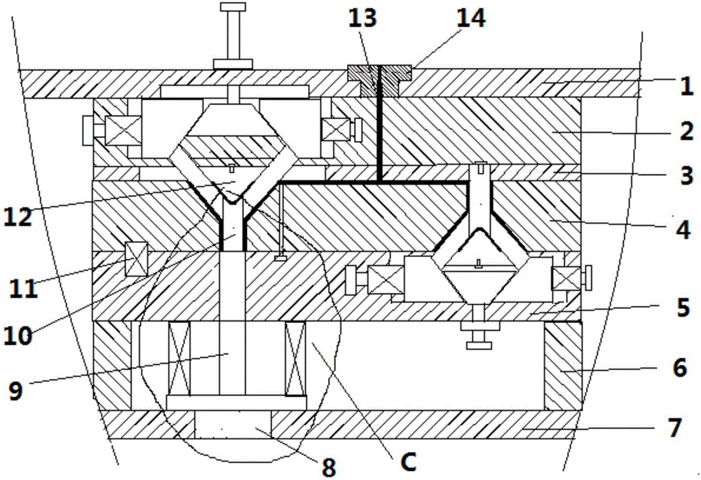
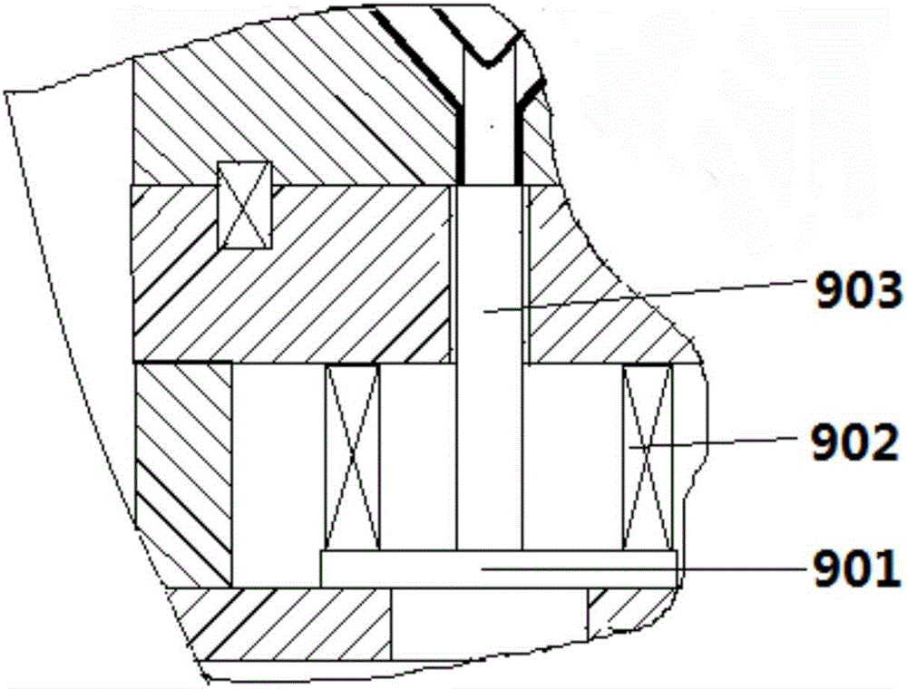
Y-shaped three-way injection mold with simple ejection structure

An injection mold, a simple technology, applied in the field of Y-shaped three-way injection molds, can solve the problems of low production efficiency, complex molds, and difficult product removal, and achieve the effect of strong practicability, small space occupation, and simple structure

Active Publication Date: 2016-12-14
佛山市科硕精密注塑有限公司
View PDF5 Cites 0 Cited by
  • Summary
  • Abstract
  • Description
  • Claims
  • Application Information

AI Technical Summary

Problems solved by technology

[0002] In the connection of some pipelines, tees are widely used, especially in today's technologically advanced society, lightweight and corrosion-resistant plastic pipe fittings are used in pipelines of all walks of life. The general application is more and more widely. In order to facilitate the mass production of this kind of plastic parts, the commonly used method is to process them in batches through injection molds, which not only saves processing costs but also saves time and effort. Therefore, injection molds are commonly used in the mass production of plastic parts. Processing method, there are many types of tees, such as straight tees, oblique tees and Y-shaped tees. For different types of tees, different molds need to be made to complete the processing. In the existing equipment, straight tees The injection molds made by the oblique tee are relatively simple and common, while for the Y-shaped tee, there are relatively few molds for making them. Because the shape is not horizontal, flat and vertical, the molds produced will be relatively complicated, and the mold It will be larger, and it is not easy to take out the product during demoulding, and the production efficiency is low. In view of this situation, the present invention proposes a Y-shaped tee injection mold with a simple ejection structure, which can produce multiple tees in one molding. Based on the simple and easy ejection structure of the workpiece, the mold is simple and takes up less space, which improves production efficiency and reduces production costs

Method used


Image

  • Y-shaped three-way injection mold with simple ejection structure
  • Y-shaped three-way injection mold with simple ejection structure

Examples


Embodiment Construction

[0023] It should be noted that, in the case of no conflict, the embodiments of the present invention and the features in the embodiments can be combined with each other.

[0024] In describing the present invention, it should be understood that the terms "center", "longitudinal", "transverse", "upper", "lower", "front", "rear", "left", "right", " The orientations or positional relationships indicated by "vertical", "horizontal", "top", "bottom", "inner" and "outer" are based on the orientations or positional relationships shown in the drawings, and are only for the convenience of describing the present invention and Simplified descriptions, rather than indicating or implying that the device or element referred to must have a particular orientation, be constructed and operate in a particular orientation, and thus should not be construed as limiting the invention. In addition, the terms "first", "second", etc. are used for descriptive purposes only, and should not be understood ...


PUM


Abstract

The invention provides a Y-shaped three-way injection mold with a simple ejection structure. The Y-shaped three-way injection mold comprises a lower mold seat, pad feet, a fixed template fixing plate, a fixed template, a movable template, a movable template fixing plate and an upper mold seat; a gate sleeve is arranged in the center of the upper mold seat; a runner is arranged along the center of the gate sleeve; a plurality of groups of Y-shaped cavities are formed in the fixed template; each group of the Y-shaped cavities comprises a positive Y-shaped part and an inverted Y-shaped part which are arranged in opposite directions; the movable template fixing plate and the fixed template fixing plate are both provided with a first mold core and a second mold core; the movable template and the fixed template are each provided with a third mold core; a first spring is fixed between the fixed template and the fixed template fixing plate; and the lower mold seat is provided with a straight ejection mechanism; and the straight ejection mechanism is composed of an ejector pin, a cushion plate and third springs. According to the Y-shaped three-way injection mold with the simple ejection structure, by reasonably arranging injection parts, a workpiece is ejected by using the simplest ejection mechanism, so that the ejection effect is better, and the production cost is saved.

Description

technical field [0001] The invention belongs to the field of injection molds, in particular to a Y-shaped tee injection mold with a simple ejection structure. Background technique [0002] In the connection of some pipelines, tees are widely used, especially in today's technologically advanced society, lightweight and corrosion-resistant plastic pipe fittings are used in pipelines of all walks of life. The general application is more and more widely. In order to facilitate the mass production of this kind of plastic parts, the commonly used method is to process them in batches through injection molds, which not only saves processing costs but also saves time and effort. Therefore, injection molds are commonly used in the mass production of plastic parts. Processing method, there are many types of tees, such as straight tees, oblique tees and Y-shaped tees. For different types of tees, different molds need to be made to complete the processing. In the existing equipment, stra...

Claims


Application Information

Patent Timeline
Patent Type & Authority Applications(China)
IPC IPC(8): B29C45/32B29C45/40
CPCB29C45/32B29C45/4005
Inventor 王孝忠
Owner 佛山市科硕精密注塑有限公司
Why Eureka
Try Eureka