Portal bucket wheel stacker and reclaimer
A bucket-wheel stacker-reclaimer and reclaimer technology, which is applied in the directions of transportation, packaging, loading/unloading, etc., can solve the problems of inability to achieve layering and cross-pile reclaiming, production capacity constraints, and storage of various materials, etc. question
- Summary
- Abstract
- Description
- Claims
- Application Information
AI Technical Summary
Problems solved by technology
Method used
Image
Examples
Embodiment 1
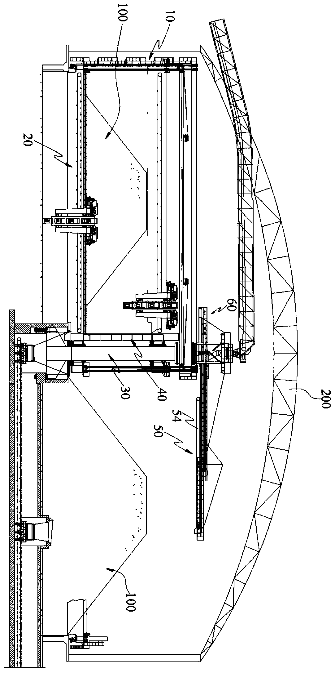
[0094] figure 1 It is a schematic diagram of a preferred embodiment of the stacker-reclaimer provided by the present invention. The stacker-reclaimer can simultaneously complete material storage, stacking and taking out, specifically, as figure 1 As shown, the working environment of the stacker-reclaimer is a circular stockyard, and the bulk stockpile stored in it is an annular stockpile 100 with a trapezoidal top, and the stockyard is surrounded by a dome 200 and an annular retaining wall; With this example,
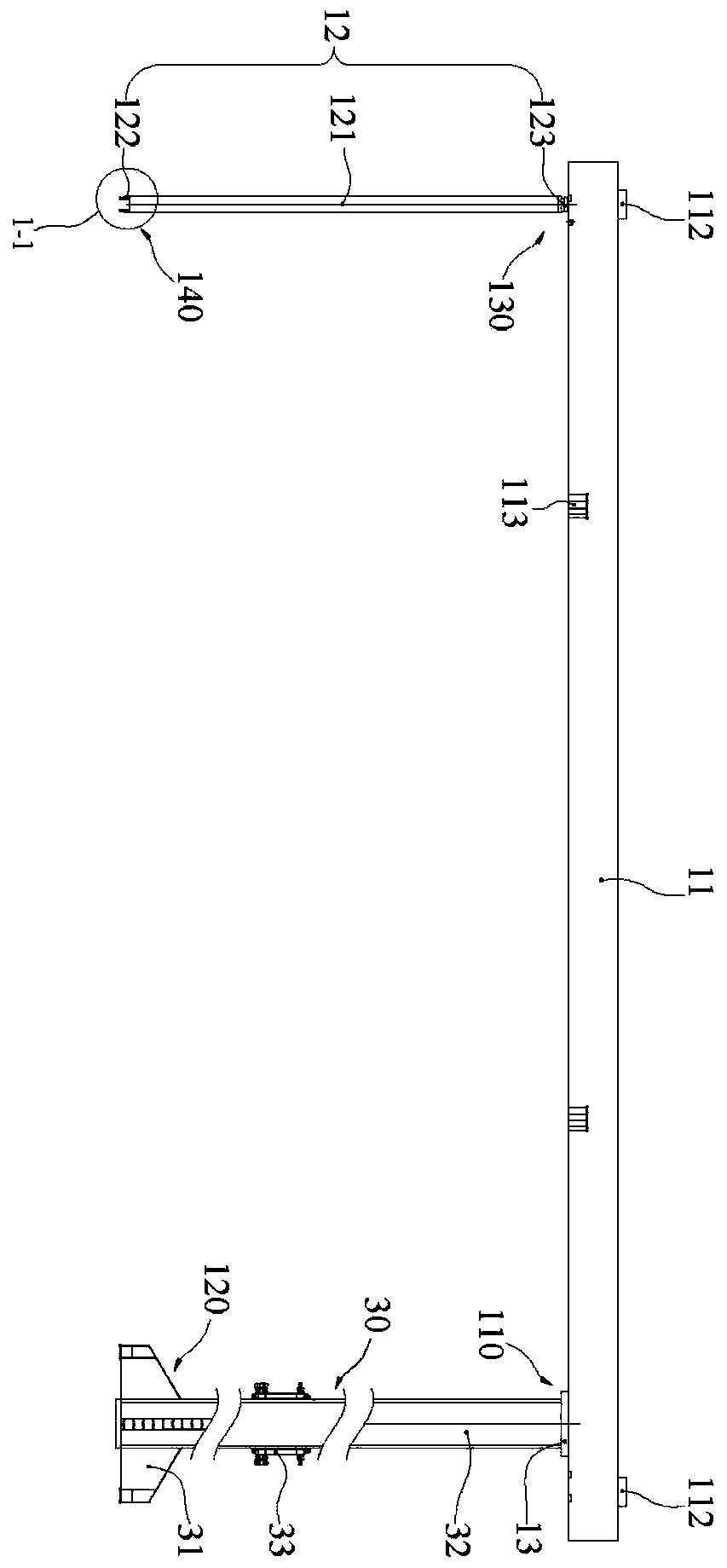
[0095] Such as figure 1 As shown, the gantry bucket wheel stacker and reclaimer includes a revolving gantry part 10, a bucket wheel reclaiming part 20, a conveying part 50 and a centering turning part 30, wherein the revolving gantry part 10 takes the span of the revolving gantry part as the radius Rotating around the centering rotary part 30, the bucket wheel retrieving part 20 and the conveying part 50 are connected to the revolving gantry part 10, wherein: the conv...
Embodiment 2
[0125] The difference between this embodiment and Embodiment 1 lies in the structure of the balance part 60 and the way and principle of realizing the balance of the cantilever beam 54 . Such as Figure 15 with Figure 16 As shown, in this embodiment, the balance part 60 includes a first pull rod 62 and a second pull rod 63 respectively arranged on both sides of the central axis 14, the first pull rod 62 is hinged with the central axis 14 and the cross arm 11 respectively, and the second pull rod 63 is hinged with central axis 14 and cantilever beam 54 respectively. The position where the first pull rod 62 is hinged to the cross arm 11 coincides with the position where the deformation of the crossbeam of the revolving gantry part 10 is the largest, thus, through the disturbance deformation of the crossbeam of the revolving mast part 10 itself, the balance of the conveying part 50 is provided. In this way, the dynamic balance of the entire conveying part can be realized witho...
Embodiment 3
[0128] The difference between this embodiment and Embodiments 1 and 2 lies in the structural form of the conveying part 50. By optimizing the structure of the conveying part 50, the two operations of retrieving and stacking are combined without additional cantilever beams 54 and balancing parts 60 and Connecting workpieces, etc., suitable for material yards where reclaiming and stacking are not carried out at the same time. What is more important is to realize the adjustable height of stacking material, the inventor has carried out further improvement for above-mentioned two preferred implementation modes, as Figure 17 with Figure 18 As shown, the delivery part 50 is located in the revolving gantry part 10 and rotates together, including a belt conveyor 51 for taking materials, a trapezoidal distribution conveyor 53, a trolley running mechanism 54 and a belt conveyor 56 for stacking, wherein the belt conveyor 51 for taking materials, Trapezoidal distributing machine 53, troll...
PUM
 Abstract
Description
Claims
Application Information
 - R&D
- Intellectual Property
- Life Sciences
- Materials
- Tech Scout
- Unparalleled Data Quality
- Higher Quality Content
- 60% Fewer Hallucinations
Browse by: Latest US Patents, China's latest patents, Technical Efficacy Thesaurus, Application Domain, Technology Topic, Popular Technical Reports.
© 2025 PatSnap. All rights reserved.Legal|Privacy policy|Modern Slavery Act Transparency Statement|Sitemap|About US| Contact US: help@patsnap.com


