
Spreading machine for hard fabric

A stretching machine and fabric technology, applied in thin material processing, textile material cutting, textiles and papermaking, etc., can solve the problems of loss of support, mismatch of height and position between movable plate and lower splint, and inconvenient movement, etc., to achieve adjustment flexible effects

Active Publication Date: 2016-12-14
伊士曼缝制机械(宁波)有限公司
View PDF8 Cites 21 Cited by
  • Summary
  • Abstract
  • Description
  • Claims
  • Application Information

AI Technical Summary

Problems solved by technology

Since the edge of the existing movable plate is in a straight line, the cloth must protrude outward from the edge of the movable plate and fall into the lower splint in order to make the chuck of the pneumatic clamp device not press the movable plate while clamping the cloth. However, the cloth protruding from the movable plate is not conducive to the smooth operation of the cloth clamping due to the loss of the support of the movable plate
[0004] In addition, the existing pneumatic clamp devices are mainly fixed by moving. Since this kind of clamp is relatively heavy, two people need to lift it up to move to the corresponding fixed position when moving, which is very inconvenient to move. Moreover, this pneumatic clamp After the jig moves to the corresponding fixed position, the height of the chuck part of the jig cannot be adjusted. Therefore, when it cooperates with the cutter and press device of the stretching machine, it is easy to cause the height position of the movable plate to not match the lower splint. The cloth clamping effect is not good, which affects the subsequent cloth cutting operation

Method used


Image

  • Spreading machine for hard fabric
  • Spreading machine for hard fabric
  • Spreading machine for hard fabric

Examples


Embodiment Construction

[0051] The present invention will be further described in detail below in conjunction with the accompanying drawings and embodiments.

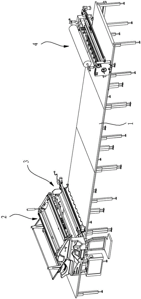
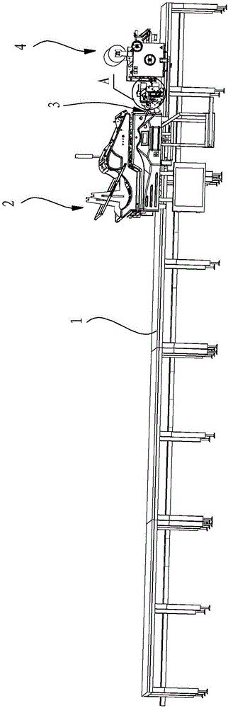
[0052] Such as Figure 1 to Figure 3 As shown, the hard fabric stretching machine in this embodiment includes a workbench 1, on which a cloth stretching device 2, a cutter pressing device 3 and a pneumatic clamping device 4 are installed in sequence, wherein the cutter pressing The cloth device 3 is always connected with the cloth pulling device 2, and the cloth pulling device 2 and the cutter pressing device 3 can move as a whole to be close to the pneumatic clamp device 4, and the cutter pressing device 3 after the approach is connected with the pneumatic clamp device 4 . The cloth spreading device in this embodiment adopts the structure of the existing cloth spreading machine, and its structure will not be described here.

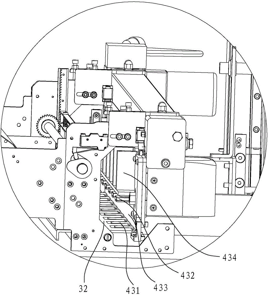
[0053] Such as Figure 4 to Figure 6 As shown, the cutter pressing device 3 in this embodiment includes a cloth sli...


PUM


Abstract

A spreading machine for hard fabric comprises a working table. A spreading device, a cutter cloth pressing device and a pneumatic clamp device are installed on the working table. The cutter cloth pressing device comprises a cloth sliding plate and a movable plate. The pneumatic clamp device comprises a chuck assembly. A first comb tooth structure is formed on the lateral side of the side, facing the pneumatic clamp device, of the movable plate. The chuck assembly comprises a lower clamping plate and an upper clamping plate. The lower clamping plate is of a second comb tooth structure. In the state that the cutter cloth pressing device moves to be connected with the pneumatic clamp device, comb teeth of the movable plate and comb teeth of the lower clamping plate are inserted in and matched with each other. Comb teeth of the upper clamping plate and comb teeth of the movable plate are completely staggered with each other in the vertical direction. Because the comb tooth structures matched with each other are formed between the movable plate and the lower clamping plate of the spreading machine for hard fabric and the comb teeth of the upper clamping plate and the comb teeth of the movable plate are completely staggered with each other in the vertical direction, after the movable plate and the lower clamping plate are in comb tooth fit, the pneumatic clamp cannot clamp the comb teeth of the movable plate while clamping cloth, and the cutter cloth pressing device can smoothly retreat.

Description

technical field [0001] The invention relates to a fabric spreading machine, in particular to a fabric spreading machine for hard fabrics. Background technique [0002] In the garment production industry, cloth drawing and cutting play a vital role. Only regular cut pieces have the opportunity to sew clothes that meet the specifications. If the cut pieces are irregular, even the best sewing machine and the best sewing It is also difficult for workers to sew high-quality clothes. Rabbing is the first process of garment making, and the quality of rabbing determines the quality of the entire production. The cloth stretching machine is an important cloth spreading and stacking tool, which can save a lot of manpower. It is mainly used for cloth stretching and cutting, so that the whole roll of cloth can be pulled out to an appropriate length, and then cut into a suitable The size of the cloth, and can achieve automatic feeding and automatic edge. When the existing stretching ma...

Claims


Application Information

Patent Timeline
Patent Type & Authority Applications(China)
IPC IPC(8): B65H20/16D06H7/00
CPCB65H20/16B65H2701/1133B65H2701/174D06H7/00
Inventor 李志沈凯伦花成达冯立庆杨嘉树
Owner 伊士曼缝制机械(宁波)有限公司
Features
  • Generate Ideas
  • Intellectual Property
  • Life Sciences
  • Materials
  • Tech Scout
  • Unparalleled Data Quality
  • Higher Quality Content
  • 60% Fewer Hallucinations
Learn More