High-speed intake and vent valve provided with water-hammer-resistant device

A high-speed technology for intake and exhaust valves, applied in the direction of valve devices, valve operation/release devices, valve fluid energy absorption devices, etc., can solve the problems of reduced flow rate, heavy weight, large volume, etc., and achieve volume reduction , prevent water hammer, and reduce weight

Inactive Publication Date: 2016-12-14
BENSV VALVE CO LTD
View PDF0 Cites 0 Cited by
  • Summary
  • Abstract
  • Description
  • Claims
  • Application Information

AI Technical Summary

Problems solved by technology

The usual high-speed intake and exhaust valves do not have an integrated anti-hammer device. The anti-hammer device is designed as an independent valve, which is large in size and heavy in weight. It is necessary to consider the influence of the entire valve on the pipeline when installed on the pipeline, and there are also a series of settings such as support. The problem
Although some anti-hammer devices installed in the valve body can alleviate the water hammer, they usually reduce the flow rate and affect the transmission efficiency of the pipeline system.

Method used


Image

  • High-speed intake and vent valve provided with water-hammer-resistant device

Examples


Embodiment 1

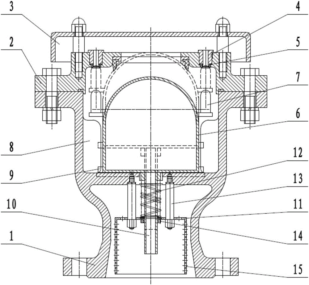
[0017] Such as figure 1 As shown, a high-speed intake and exhaust valve with a built-in anti-hammer device includes a valve body 1, a valve cover 2 is fixed on the top of the valve body 1, and a sealing ring is provided between the valve body 1 and the valve cover 2 , the top of the valve cover 2 is fixed with a gland 3, and the valve cover 2 is provided with multiple groups of micro-exhaust valve seats 4, and the bottom of the micro-exhaust valve seat 4 is provided with a micro-exhaust valve seat sealing ring 5, The valve body 1 includes an upper body cavity and a lower inlet end, a partition is provided between the body cavity and the inlet end, and an anti-hammer spool 11 is arranged inside the inlet end, and the anti-hammer spool 11 The four sides and the upper end surface are provided with a plurality of through holes 15 arranged in an orderly manner. The center of the upper end surface of the waterproof hammer valve core 11 is provided with a buffer spring 12, and the bo...

Embodiment 2

[0022] Such as figure 1 As shown, a high-speed intake and exhaust valve with a built-in anti-hammer device includes a valve body 1, a valve cover 2 is fixed on the top of the valve body 1, and a sealing ring is provided between the valve body 1 and the valve cover 2 , the top of the valve cover 2 is fixed with a gland 3, and the valve cover 2 is provided with multiple groups of micro-exhaust valve seats 4, and the bottom of the micro-exhaust valve seat 4 is provided with a micro-exhaust valve seat sealing ring 5, The valve body 1 includes an upper body cavity and a lower inlet end, a partition is provided between the body cavity and the inlet end, and an anti-hammer spool 11 is arranged inside the inlet end, and the anti-hammer spool 11 The four sides and the upper end surface are provided with a plurality of through holes 15 arranged in an orderly manner. The center of the upper end surface of the waterproof hammer valve core 11 is provided with a buffer spring 12, and the bo...

Embodiment 3

[0027] Such as figure 1 As shown, a high-speed intake and exhaust valve with a built-in anti-hammer device includes a valve body 1, a valve cover 2 is fixed on the top of the valve body 1, and a sealing ring is provided between the valve body 1 and the valve cover 2 , the top of the valve cover 2 is fixed with a gland 3, and the valve cover 2 is provided with multiple groups of micro-exhaust valve seats 4, and the bottom of the micro-exhaust valve seat 4 is provided with a micro-exhaust valve seat sealing ring 5, The valve body 1 includes an upper body cavity and a lower inlet end, a partition is provided between the body cavity and the inlet end, and an anti-hammer spool 11 is arranged inside the inlet end, and the anti-hammer spool 11 The four sides and the upper end surface are provided with a plurality of through holes 15 arranged in an orderly manner. The center of the upper end surface of the waterproof hammer valve core 11 is provided with a buffer spring 12, and the bo...


PUM


Abstract

The invention relates to a high-speed intake and vent valve provided with a water-hammer-resistant device. The high-speed intake and vent valve comprises a valve body, wherein a valve deck is fixed on the top of the valve body; trace vent valve seats are arranged on the valve deck; the valve body is internally provided with a body cavity and an inlet end; a clapboard is arranged between the body cavity and the inlet end; a water-hammer-resistant valve element is arranged in the inlet end; through holes are formed in the water-hammer-resistant valve element; a buffer spring is arranged in the center of the upper end surface of the water-hammer-resistant valve element; valve element guiding rods are separately arranged on two sides of the upper end surface of the water-hammer-resistant valve element; a floating ball is arranged in the body cavity; and a guiding rod is fixed on the bottom of the floating ball. According to the high-speed intake and vent valve, the water-hammer-resistant device is arranged in the intake and vent valve, so that the size of the valve is reduced, and the weight of the valve is reduced. The total of the areas of the through holes in the water-hammer-resistant valve element is larger than the area of the path of the valve, so that the flow of passing fluid is increased; and great energy which is generated suddenly in the pipeline is slowly absorbed by the water-hammer-resistant valve element and the buffer spring on the water-hammer-resistant valve element, so that a water hammer is effectively avoided.

Description

technical field [0001] The invention relates to the production field of intake and exhaust valves, in particular to a high-speed intake and exhaust valve with a built-in anti-hammer device. Background technique [0002] When the valve is suddenly opened or closed, a large flow of water is generated, causing water hammer. Since the pipe wall is smooth, under the impact of the inertia of the water flow, the hydraulic force quickly reaches the maximum, causing damage to the pipe and valve body. The usual high-speed intake and exhaust valves do not have an integrated anti-hammer device. The anti-hammer device is designed as an independent valve, which is large in size and heavy in weight. It is necessary to consider the influence of the entire valve on the pipeline when installed on the pipeline, and there are also a series of settings such as support. The problem. Although some anti-hammer devices installed in the valve body can alleviate the water hammer, they usually reduce...

Claims


Application Information

Patent Timeline
Patent Type & Authority Applications(China)
IPC IPC(8): F16K47/02F16K31/20
CPCF16K47/023F16K31/20
Inventor 廖志芳常永红李志鹏王东辉王荣辉王东福黎文斌
Owner BENSV VALVE CO LTD
Why Eureka
Try Eureka