
Spiral pipe steam generator

A technology of a steam generator and a spiral tube, which is applied in the directions of steam generation, steam generation device, steam generation method, etc., can solve the problems of long heating time, large energy consumption, low efficiency, etc., and achieves low water consumption, reduced energy consumption, produce fast effects

Pending Publication Date: 2016-12-14
深圳宝联智汇科技有限公司
View PDF6 Cites 0 Cited by
  • Summary
  • Abstract
  • Description
  • Claims
  • Application Information

AI Technical Summary

Problems solved by technology

Whether it is a built-in or an external electric heating type, a large amount of water needs to be heated. The first disadvantage is that it needs to consume a lot of energy for heating. The second disadvantage is that it takes a long time to heat and it is difficult to generate steam instantly. The efficiency is not high. There is a lot of scale, which is prone to problems

Method used


Image

  • Spiral pipe steam generator
  • Spiral pipe steam generator
  • Spiral pipe steam generator

Examples


Embodiment 1

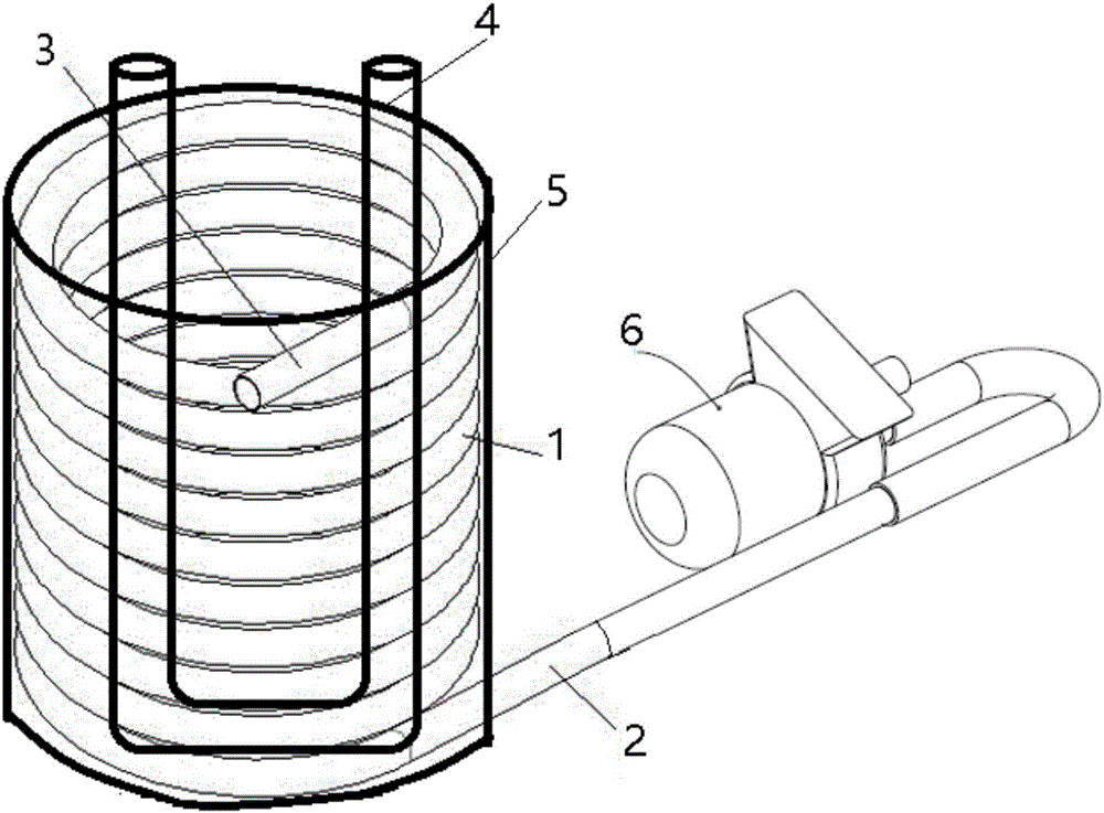
[0027] Such as figure 1 As shown, a spiral tube steam generator includes a heating element U-shaped tube 4, a spiral tube 1, and a water pump 6; wherein, the water pump 6 communicates with the water inlet 2 at one end of the spiral tube, and the other end of the spiral tube is a steam outlet 3 ; The U-shaped tube 4 of the heating assembly is located in the spiral ring of the spiral tube 1, and the outer periphery of the spiral tube 1 is also provided with a heat-preserving layer 5 .

[0028] Further, the steam outlet 3 is connected to the steam inlet nozzle on the side wall of the steam pot, and high-temperature steam can be fed in from the side wall of the steam pot. Example 2

Embodiment 2

[0029] Such as figure 1 and 2 As shown, a helical tube steam generator, a helical tube steam generator, includes a heating element U-shaped tube 4, a helical tube 1, and a water pump; wherein, the water pump communicates with the water inlet 2 at one end of the helical tube, and the other end of the helical tube One end is a steam outlet 3 ; the U-shaped tube 4 of the heating element is located in the spiral ring of the spiral tube 1 , and a heat-preserving layer 5 is provided on the periphery of the spiral tube 1 .

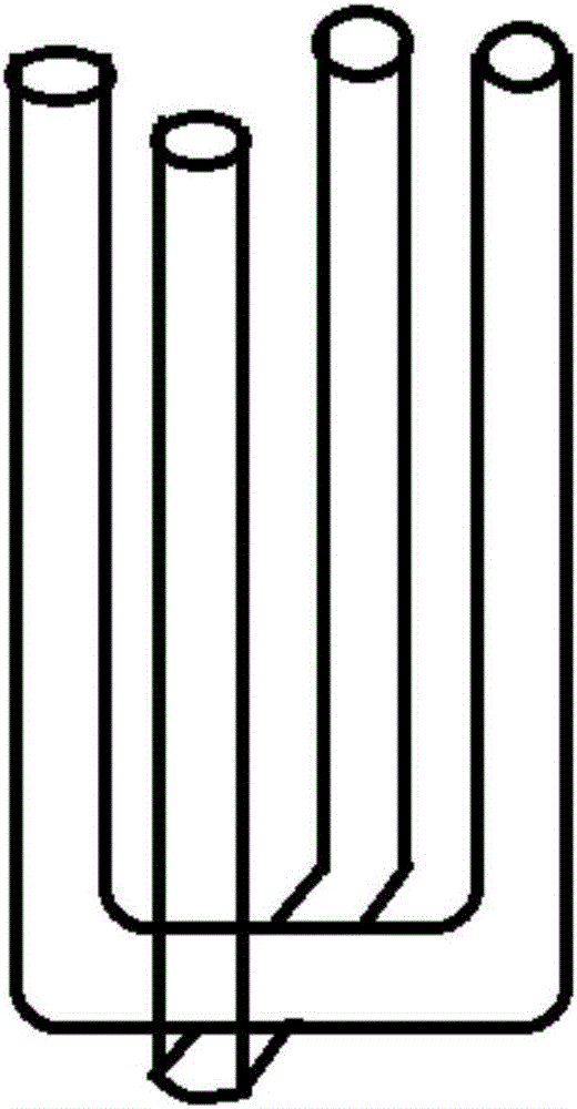
[0030] Such as figure 2 As shown, preferably, there are two U-shaped tubes, which are arranged crosswise.

Embodiment 3

[0032] Such as figure 1 As shown, a spiral tube steam generator includes a heating element U-shaped tube 4, a spiral tube 1, and a water pump 6; wherein, the water pump 6 communicates with the water inlet 2 at one end of the spiral tube, and the other end of the spiral tube is a steam outlet 3 ; The U-shaped tube 4 of the heating assembly is located in the spiral ring of the spiral tube 1, and the outer periphery of the spiral tube 1 is also provided with a heat-preserving layer 5 .

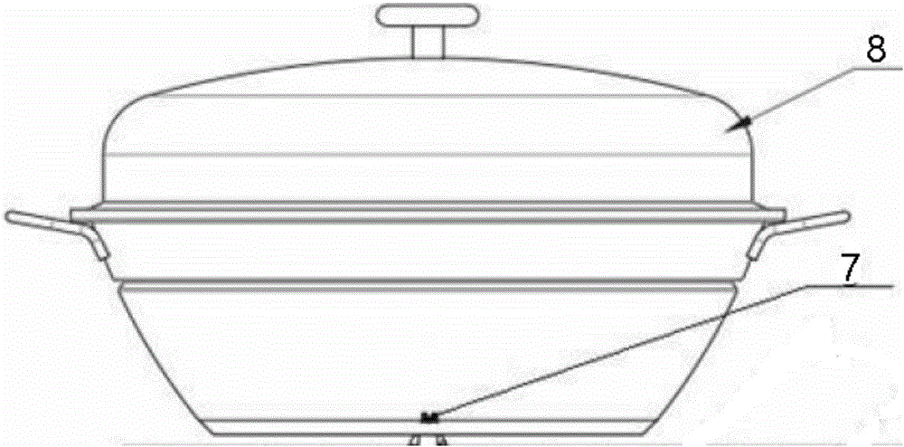
[0033] Such as image 3 As shown, the steam outlet 3 is connected to the steam inlet nozzle 7 at the bottom of the steam pot, and high-temperature steam can be fed from the bottom of the steam pot, and also includes a pot cover 8 for cooking food.


PUM


Abstract

The invention provides a spiral pipe steam generator, aims to overcome the defects in the prior art, and use less water for quickly generating steam to reduce energy consumption and limescale. In order to realize the purpose, the invention adopts the following technical scheme: the spiral pipe steam generator comprises a heating module, a spiral pipe and a water pump, wherein the water pump is communicated with a water inlet at one end of the spiral pipe; the other end of the spiral pipe is a steam outlet; the heating module is positioned in a spiral ring of the spiral pipe; and a heating layer is arranged at the outer periphery of the spiral pipe.

Description

technical field [0001] The invention relates to a steam generator, in particular to a spiral tube steam generator. Background technique [0002] The existing catering industry is nothing more than steaming, boiling or frying. For the processing methods of steaming and boiling, some use direct fire heating. , and then put a steamer in the iron pot, put the food in the steamer grid, directly heat the bottom of the pot through firewood or coal fire, boil the water in the pot, and steam the food in the steamer with the steam generated by the water; if it is Cooking does not need a steamer, but directly add water to the iron pot to cook. This method is very traditional. Due to its low energy utilization rate and great environmental pollution, it has been gradually eliminated. Now except in rural areas, In addition to being used for weddings and ceremonies, it is also difficult to see in various catering industries in the city. [0003] Most of the modern catering industry uses ...

Claims


Application Information

Patent Timeline
Patent Type & Authority Applications(China)
IPC IPC(8): F22B33/00F22B35/00F22B37/42F22B37/10F22B1/28
CPCF22B1/28F22B33/00F22B35/00F22B37/10F22B37/42
Inventor 阮塔源
Owner 深圳宝联智汇科技有限公司
Learn More