
Linear guide rail precision detecting device and method

A technology of precision detection and linear guide rail, which is applied in the field of measurement, can solve the problems of measurement efficiency and measurement accuracy, repeatability, increase of economic cost and maintenance cost, and poor repeatability of measurement results, so as to reduce labor intensity and study time, Effect of vibration is small, and the effect of reducing processing cost

Active Publication Date: 2016-12-14
NANJING UNIV OF SCI & TECH +1
View PDF7 Cites 4 Cited by
  • Summary
  • Abstract
  • Description
  • Claims
  • Application Information

AI Technical Summary

Problems solved by technology

[0002] At present, the accuracy measurement of rolling linear guides is mostly carried out by manual measurement or contact sensors. When manually measuring the parallelism of the guide rail raceways, the guide rail is clamped on the fixture of the measuring flat plate, and the table base is connected to the reference surface of the guide rail side and the installation plane of the guide rail. Align, and align the meter head with the raceway surface of the guide rail, and then move the meter base to measure. The difference between the measured maximum and minimum values ​​is the parallelism error of the guide rail raceway. The quality requirements of the personnel are high and the repeatability of the measurement results is poor; the Chinese invention publication number CN103438839A, the name is: a linear guide rail precision automatic measurement device and its measurement method, the patent introduces the use of non-contact sensors to measure the guide rail accuracy, the sensor is in contact Pneumatic components are installed on the type sensor so that it does not touch the measured object during the non-working period. During the measurement, the standard slider equipped with this type of sensor moves at a certain interval to realize the measurement of the height and parallelism of the measured guide rail. , this method needs to make corresponding standard guide rails and standard sliders when measuring different types of guide rails, which increases economic costs and maintenance costs
[0003] To sum up, there are few measurement items covered by various guideway precision measuring instruments used at this stage, especially for the measurement of raceway-related precision, and the measurement efficiency, measurement accuracy and repeatability need to be improved.

Method used


Image

  • Linear guide rail precision detecting device and method
  • Linear guide rail precision detecting device and method
  • Linear guide rail precision detecting device and method

Examples


Embodiment Construction

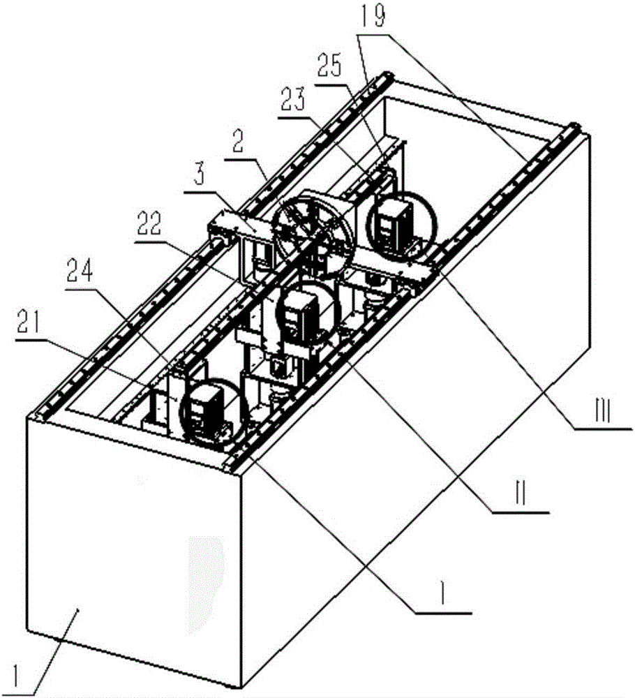
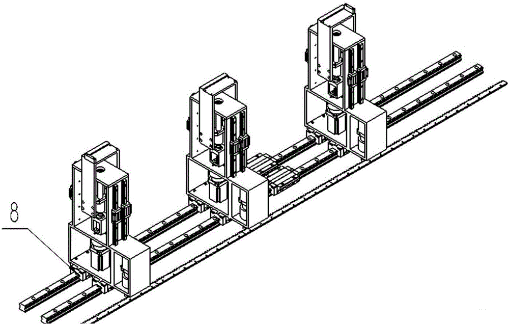
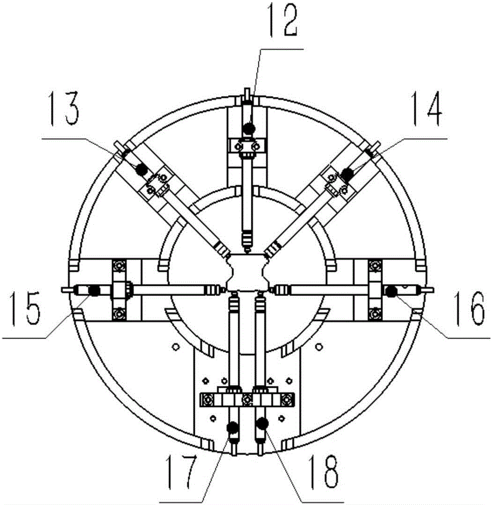
[0019] combine figure 1 , figure 2 , image 3 , a linear guide rail accuracy detection device of the present invention, comprising a bed 1, a group of linear guide rail pairs 19 parallel to each other are arranged on the left and right sides of the bed 1, and the bridge frame 3 is fixedly connected above the two sets of linear guide rail pairs, and the bridge frame 3 The driving device is arranged below the bridge frame 3, and the disc measurement frame 2 is fixedly installed in the middle of the bridge frame 2. The first non-contact displacement sensor 12, the second non-contact displacement sensor 13, and the third non-contact displacement sensor 14 are arranged on the measurement frame 2. , the fourth non-contact displacement sensor 15, the fifth non-contact displacement sensor 16, the sixth non-contact displacement sensor 17 and the seventh non-contact displacement sensor 18, the above-mentioned seven non-contact displacement sensors are respectively aligned to the measu...


PUM


Abstract

The invention discloses a linear guide rail precision detecting device and method. The device comprises a bed, two linear guide pairs in parallel with each other are arranged at left and right sides of the bed respectively, a bridge stand is fixedly connected to the guide pairs and arranged on the guide pairs, a driver unit is arranged in left lower position of the bridge stand, a disk measuring rack is fixedly mounted in the middle of the bridge stand, seven non-contact displacement sensors are arranged on the measuring rack in a symmetrical manner and are aligned with the top center of a detected guide rail, left and right raceways in the upper of the detected guide rail, a reference side surface of the detected guide rail, a non-reference side surface of the detected guide rail and left and right sides, in the width direction, of the bottom of the detected guide rail respectively, a linear guide pair is arranged in the bottom of the bed, three identical axis-Z linear slide units which can move along the length direction of the bed independently are fixedly connected to the linear guide pair and arranged on the linear guide pair, and a carriage which can hold the detected guide rail is arranged on the slide units. The detecting device is simple in structure, the guide rail can be fixed needless of bolts, the manufacture cost is reduced, and the measuring efficiency can be improved.

Description

technical field [0001] The invention relates to the field of measurement technology, in particular to a linear guide rail accuracy measurement device and a measurement method thereof. Background technique [0002] At present, the accuracy measurement of rolling linear guides is mostly carried out by manual measurement or contact sensors. When manually measuring the parallelism of the guide rail raceways, the guide rail is clamped on the fixture of the measuring flat plate, and the table base is connected to the reference surface of the guide rail side and the installation plane of the guide rail. Align, and align the meter head with the raceway surface of the guide rail, and then move the meter base to measure. The difference between the measured maximum and minimum values ​​is the parallelism error of the guide rail raceway. The quality requirements of the personnel are high and the repeatability of the measurement results is poor; the Chinese invention publication number C...

Claims


Application Information

Patent Timeline
Patent Type & Authority Applications(China)
IPC IPC(8): G01B13/02G01B13/18
CPCG01B13/02G01B13/18
Inventor 欧屹王柳冯虎田
Owner NANJING UNIV OF SCI & TECH
Learn More