Bearing axial clearance automatic detection device

An axial clearance and automatic detection technology, applied in measuring devices, instruments, etc., can solve the problems of human factors, unqualified outflow, low efficiency, etc., to ensure detection accuracy, avoid unqualified products from the factory, and improve detection efficiency Effect

Active Publication Date: 2016-12-14
浙江斯菱汽车轴承股份有限公司
View PDF5 Cites 0 Cited by
  • Summary
  • Abstract
  • Description
  • Claims
  • Application Information

AI Technical Summary

Problems solved by technology

The bearing clearance test needs to be carried out after its assembly and molding. The bearing clearance test requires the bearing to have a certain range of clearance. If the clearance is too large or too small, it will affect the performance of the bearing and be listed as unqualified. The existing bearing Clearance detection, especially the axial clearance of bearings, is generally detected manually. Manual detection is not only inefficient, but also greatly affected by human factors, and unqualified outflows are prone to occur

Method used


Image

  • Bearing axial clearance automatic detection device
  • Bearing axial clearance automatic detection device
  • Bearing axial clearance automatic detection device

Examples


Embodiment Construction

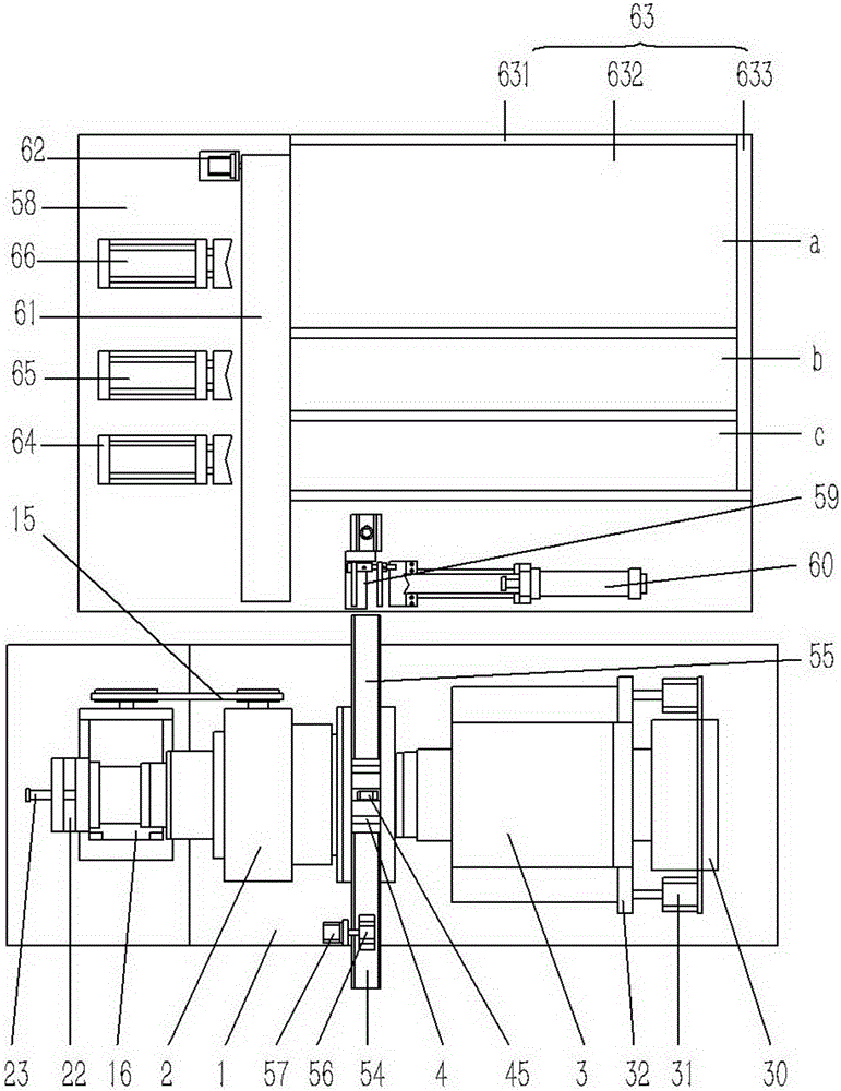
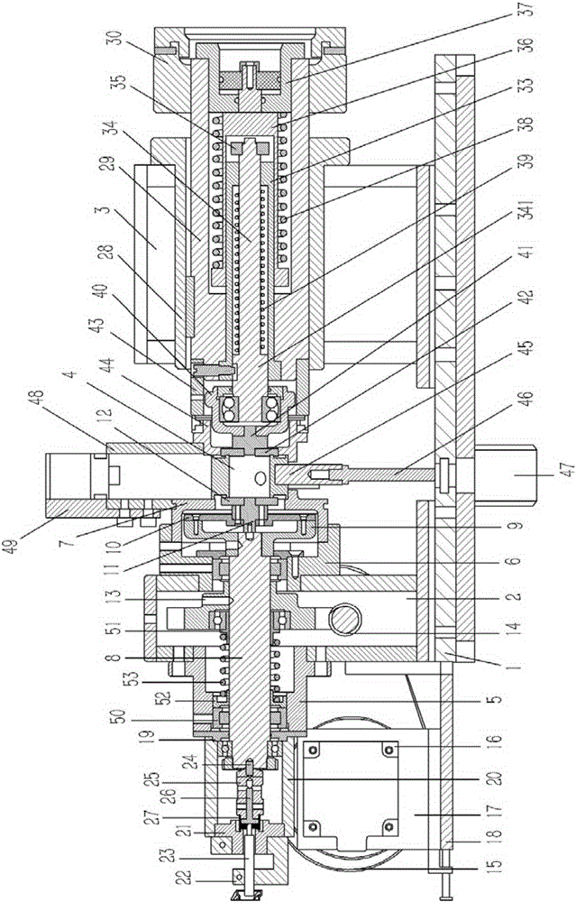
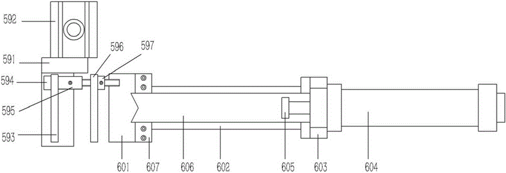
[0031] Example: see Figures 1 to 3As shown in the figure, an automatic testing device for bearing axial clearance includes a testing platform 1, which is fixed on the testing frame, and the left and right ends of the testing platform 1 are respectively fixed with a left fixing seat 2 and a right fixing seat 3. The left and right end surfaces of the left fixing seat 2 are respectively fixed with a concentric left guide ring sleeve 5 and a right guide ring sleeve 6, and the right guide ring sleeve 6 is fixedly connected with a left positioning ring sleeve 7, and the left guide ring sleeve 5, The left fixed seat 2 and the right guide ring sleeve 6 are plugged with a left positioning shaft 8, and the right end of the left positioning shaft 8 stretches out from the right guide ring sleeve 6 and is plugged and fixed on the positioning disc 9, and the right end surface of the positioning disc 9 is fixed with a Circular connection plate 10, the center of connection plate 10 is insert...


PUM


Abstract

The invention relates to a bearing axial clearance automatic detection device. The bearing axial clearance automatic detection device comprises a detection platform, the detection platform is fixed on a detection frame, the left end of the detection platform is fixed with a left mounting base, and the right end of the detection platform is fixed with a right mounting base. The left end face of the left mounting base is fixed with a concentric left guiding loop, the right end face of the left mounting base is fixed with a concentric right guiding loop, the right guiding loop is fixedly connected with a left positioning loop, a left positioning shaft is inserted into the left guiding loop, the left mounting base and the right guiding loop, and the right end of the left positioning shaft stretches out of the right guiding loop and is fixed on a positioning disc in an inserted manner. The right end face of the positioning disc is fixed with a round connection board, a crossed left top block is fixed on the center of the connection board in an inserted manner, a round left top plate is fixed on the right end of the left top block in an inserted manner, a turbine is fixed on the left positioning shaft in the left mounting base in a sleeved manner, and the lower end of the turbine is engaged with a worm. With respect to the bearing axial clearance detection device, manual detection is replaced by automatic detection, the detection efficiency can be improved, the detection precision is guaranteed, and unaccepted products are prevented from leaving factory.

Description

Technical field: [0001] The invention relates to the technical field of bearing testing equipment, and more specifically relates to an automatic testing equipment for bearing axial clearance. Background technique: [0002] Bearings are an important part of contemporary mechanical equipment; their friction properties can be divided into two categories: sliding bearings and rolling bearings. The bearing clearance test needs to be carried out after its assembly and molding. The bearing clearance test requires the bearing to have a certain range of clearance. If the clearance is too large or too small, it will affect the performance of the bearing and be listed as unqualified. The existing bearing Clearance detection, especially the axial clearance of bearings, is generally detected manually. Manual detection is not only inefficient, but also greatly affected by human factors, and unqualified outflows are prone to occur. Invention content: [0003] The purpose of the present ...

Claims


Application Information

Patent Timeline
IPC IPC(8): G01B21/16
CPCG01B21/16
Inventor 杨伟峰徐玲娜
Owner 浙江斯菱汽车轴承股份有限公司
Why Eureka
Try Eureka